looking for a way to design windband couplers
Derek
I think you can do that in stripline, you need to overlap multiple sections.
Of course, a Wilkensen power splitter will give 3 dB of coupling over that bandwidth easily--just not directional.
Biff44,
Are you sure that stripline style can reach this function? other limitation is that it can stand power surge of at least 500W. Do you have any paper on using of stripline espcially on windband coupler application. thanks.
Total structure is:
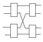
function: windband signla at arbitrary input port can pass through couplers to arbitrary outport port.
IL is less than 7dB at any path
power :500W
frequency ranged from 800M to 2.1G
RL: at least -18dB
Added after 50 minutes:
Urgently need a solution, branchline? microstrip or stripline? anyone can help me? requirement is appeared above.
500W? Didn't you think that would be an important detail to tell us about?
Use slabline with thermally conductive dielectric.
No more details to tell you about power handling capacity due to too simple spec. just knew it is for basestation application.
Help help help !
nobody knew about this?
The given structure is not simple coupler.
Please explain more on the function of each block and why cross over is needed etc.
Kspalla,
the whole structure consist of 4 2-to-2 couplers realize function: any input(left side) signal flowed can get to arbitrary output port(right). In fact, question is how to design a boardband 2in-2out couplers? if this can be done, the total will be the combination of it.
It is not that simple as you think.
Let assume that you have the best coupler 2in-2out coupler with you meeting all the requirements.
But when you connect them together as shown above they may not contribute the same as a whole.
I recollect this hybrid function similar to monopole comparator in RADAR circuit .
Do you have a good ideal? how do I design such a wideband coupler? microstrip or stripline?
From my Knowledge you should try broad side coupler in suspended air strip line.
Are suspended air strip line you meationed same trace on both side of pcb board with same air space room away from box? Do you have concrete design guide?
Check this paper
broad-band coaxial directional couplers for high-power applications
Teppati, V.; Goano, M.; Ferrero, A.; Niculae, V.; Olivieri, A.; Ghione, G.
IEEE MTT
Check this
1)
http://www.freepatentsonline.com/3701057.html
2)
http://www.physicsforums.com/archive.../t-175683.html
thanks Abhishekabs. But my boss expected to make a combiner design with pcb board like microstrip or anything else related to pcb. as Kspalla said, suspended air stripline may be applied to design, but how do?
Almost 1 year back I saw one paper on broadband directional coupler.
The range was 1-18GHz I guess.
I don't remember exactly but The technique uses teeth like structures.
I will attach that paper if I find it.
The simulation was made in AWR I guess.
Try to search this keywords in google I am sure you will find the document.
You can use same technique but use suspended air strip line insted of microstrip.
Added after 29 minutes:
I have found one paper.
I hope this will help you
Best of luck
Abhishekabs
Thanks Abhishekabs for kindly help, but IL(coupled coef)of 2in-2out couplers I need have to be below 3.5dB from 800M to 2.2G, directional couplers are unlikely to achieve I guess, maybe branchline structrue is a way but I dont know.