momentum via setup in inductor&transformer simulation
------Strip m6 (thickness expansion down)
D5 [VIA] via5
------Strip m5
When I check the structure in 3D view, I found via5 starts from top surface of m5 to the top surface of m6. However, via5 is assumed inserted between top surface of m5 and the bottom surface of m6. I guess it is because "thickness expansion down" option of m6, which expand the dielectric layer with the same thickness of m6 and with the same permittivity of D5.
Does anyone have experience to solve this problem? Thanks.
Share the piece of design.
Not able to understand
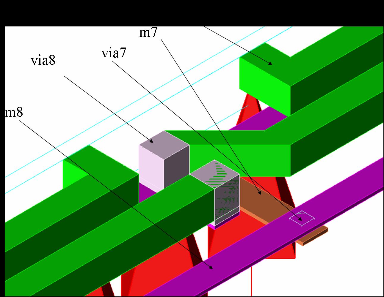
I've aksed Agilent supporting engineer. He confirmed my set-up is correct and this "error" is result by Momentum. In fact, Momentum is 2-D simulator. So, when we use thickness expansion of metal trace, such "error" will happen. Anyway, the Momentum simulation results are close to those by Sonnet. Here is 3-D structure of the transformer I simulated. As shown in the picture, via8 (grey) is overlaid with M9 (green). But, actually, via8 should only reach to the bottom of M9.
It is no ware related to M5, M6 and V5 problem.
Is it a fresh request?
Am sorry to say that confused.
Sorry to make you confused. M5, M6 and via5 listed in the first post are M8, M9 and via8 shown in 3-D structure. Thanks.
In this case V7 is more valid than V8.
Correct the stackup
Thanks for reply, kspalla. M9 has to be set "thickness expasion down" coz its dielectric constant (the dielectric between M9) is same with that between M8 and M9 but different with it above M9.
- Distance between air coil inductors
- How is the maximum inductor value in a technology process is determined
- Transmission Line vs Lumped Inductor Choice in Distributed power Amplifier Design
- Why the inductor equation is different in this paper
- Why an input inductor required in all GPS LNA?
- How to realize inductor from transmission line (micro-strip and CPW lines)