Why the inductor equation is different in this paper
Yes, expression looks erroneous at first sight. L and C in Z0 formula are per unit length, e.g. per amplifier stage.
So the correct equation for Lb in equation (2) is without /2
This is not transmission line.
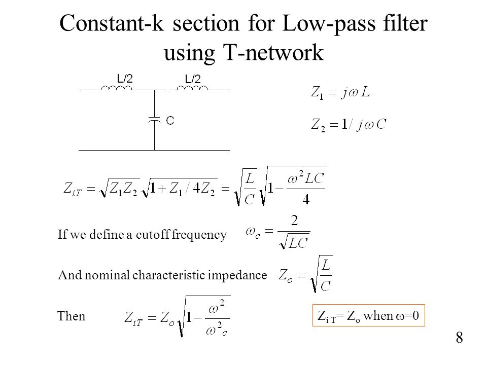
This is a cascaded connection of constant K section(L/2, C/2).
Understand things correctly,
This is very true for all your posts.
I think it is, but why don't you check yourself which solution achieves better impedance matching?
True. I should think and imagine more.

[found at: slideplayer. com/ slide /4173361 /13 /images /8 /Constant-k+section+for+Low-pass+filter+using+T-network.jpg]
Delay line in your figure is composed from 8 sections of Constant-K(L/2, C/2).
Never 5 sections.
No.
This is two sections of Constant-K
Unit section of Constant-K is L-network.
Two L-network constitute T or PI.
The delay matching by using lumped components using the approach shown in the figure completely disregards the effect of Cbc. Also, Cbe varies quiet a bit with the instantaneous voltage on the base. Does it work for large input powers?
This figure shows only concept.
I don't think distributed amplifier of BJT is possible, even if cascode structure is used as unit amplifier.
