hfss yagi design tutorial
plz plz dear friends
may be, i can send to u a simple project. but after monday.
need tutorial of how to simulate yagi antenna
yagi is a simple antenna.u start with a dipole for your omni directional patterns.followed by
The director/s is the shortest of the parasitic elements and this end of the Yagi is aimed at the receiving station. It is resonant slightly higher in frequency than the driven element, and its length will be about 5% shorter, progressively than the driven element. The director/s length/s can vary, depending upon the director spacing, the number of directors used in the antenna, the desired pattern, pattern bandwidth and element diameter. The number of directors that can be used are determined by the physical size (length) of the supporting boom needed by your design.
The reflector is the element that is placed at the rear of the driven element (The dipole). It's resonant frequency is lower, and its length is approximately 5% longer than the driven element. It's length will vary depending on the spacing and the element diameter. The spacing of the reflector will be between .1 wavelength and .25 wavelength. It's spacing will depend upon the gain, bandwidth, F/B ratio, and sidelobe pattern requirements of the final antenna design.
hope this will help.if not i can do a quick simulation for you.
Sajid Mohammed.
There is example of simulation YAGI antenna in EMC Studio
some desprition is shown below.
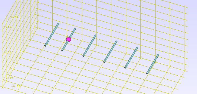
some details:L1 = 0.475*lampda
L2 = 0.46*lambda
L3 = 0.44*lambda
L4 = 0.44*lambda
L5 = 0.43*lambda
L6 = 0.4*lambda
x1 = 0.25*lambda
x2 = 0.31*lambda
x3 = 0.31*lambda
x4 = 0.31*lambda
x5 = 0.32*lambda
first dipole is reflector, second is driven dipole and other are directors
the references are balanis and modern antenna design book
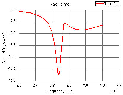
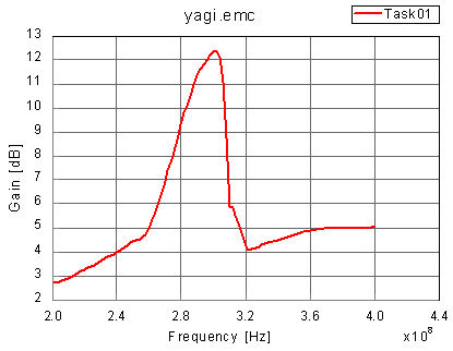
for frequency 300MHz model constructed in EMC Studio is shown
the results of S11 and GAIN are shown