why vco phase noise reduce drastically when using ldo
Look at this http://www.maxim-ic.com/app-notes/index.mvp/id/3656
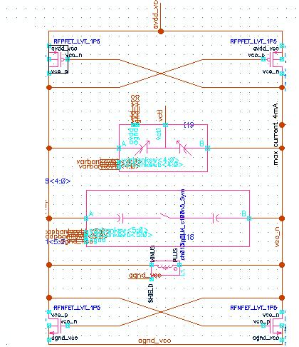
This is my vco. this structure is sensitive to vdd noise?
are you connecting LDO to your VCO chip/circuit externally? or you are doing simulation only?
If you are connecting LDO externally then link provided by E-Design is good.
LDO is on chip. And I only do simulation.
Is there any decoupling capacitor at the output of your voltage regulator ? If there isn't , connect proper one conserving stability..
So ,in simulation, with an ideal Voltage source P-N is good but when you put in
a "Model" of a non-ideal Voltage source P-N get worse?
VCO have Kvco in MHz/V right? When the bais for the VCO changes this can effect the value of Fvco. So say a with a model LDO you have:
VDD = 5V + (noise 0.001V*sin(ωt))
If noise gets on to the tuning line, your Fvco = N*Fref + Noise*Kvco
Kvco ~ 10MHz - 60MHz per Volt, & noise ~ 0.1 -10mV --> 1kHz - 600kHz
@ 5V (Ideal VDD) Fvco = 1.3GHz ! --> Grate P-N !
Now with the LDO
@ 5.001 - 4.999V Fvco = 1.30005 - 1.29995 GHz -->Not so great
So any noise in the circuit can cause P-N issues. Using an Ideal VDD is not wise
when modeling circuits that are very noise sensitive.
Cheers
There is nothing per se wrong with a LDO regulator (assuming it is linear, and not a switching regulator). What is probably wrong is the voltage reference inside of the regulator circuit (bandgap, etc). You want to bring that voltage reference outside of the chip thru a series resistor, where you can then hang a 1 uF capacitor to ground on it. This will drop its noise level to a reasonable level.