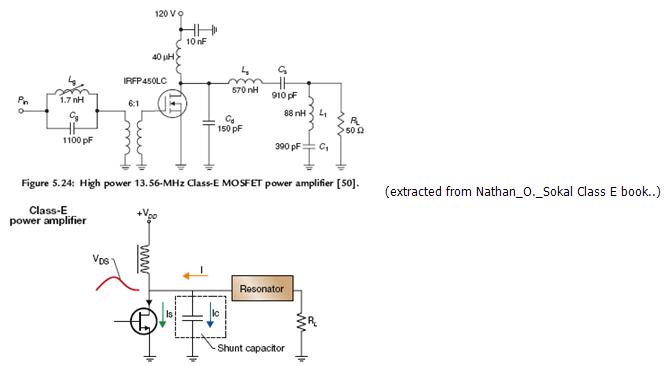
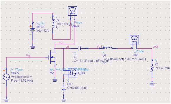
Class E power amplifier operating at 13.56Mhz
The series LC should match the input frequency.
How about the value of L at drain and shunt C value?
For single ended design, the component should only include series LC, L at drain and shunt C across drain source right?
Resonating component will be C at drain source and series LC?
or only the series LC?
Electronic amplifier - Wikipedia, the free encyclopedia
http://www.ixysrf.com/pdf/switch_mod...apprf_1150.pdf
http://www.its.caltech.edu/~mmic/res...ers/ClassE.pdf
https://www.cosic.esat.kuleuven.be/p...ticle-1180.pdf
hi vfone, thanks for your files. i already have the papers..they are useful but how do we calculate the resonant frequency for the series LC?
For the series LC at load arm that is to resonate at f0 = 13.56Mhz, I can just calculate based on XL = XC which eventually get W0 = 1/sqrtLC right?
The value of Cd should be the parasitic C of the MOSFET when running at Vgs = 10V + some value?
Yes, you can find series LC using, fo = 1/sqrtLC.
Cd is not the intrinsic capacitance of the MOSFET, but it is in parallel with it. If the internal C of the MOSFET is to high, the device is not suitable for working frequency.
Also Cs has a higher limit in value, to be able to get the proper I/V waveforms, which are very important in a Class-E PA.
A capacitor placed in parallel will bring down the total capacitance or it will bring up the total capacitance as such total cap seen at Cds is Cd+MOSFET internal Cap? pardon this question but i was in fact looking around for this answer..
Parallel means it will bring up total capacitance. The circuit needs some tuning to get the maximum performance (especially for good efficiency).
thanks vfone.
how do we judge if the power amplifier is performing correctly?
can we just judge from any amplification from Vout (output taken at rload) / Vs (example sine input at the gate input).
Please also correct me if i am wrong..
1) based on the irf510 datasheet i need at least a Vgs of 5V to get some Id flowing, then only the series LC will work right? A sine input of 20Vpp should get some current flowing right?
2) how would the current after the RFC be like? damped oscillations which is like a DC and then the output current just before Rload will be Sine. is this correct?
The main reason building Class-E PA is efficiency. So, if you get the output power, is stable, and get very good efficiency, means the PA is working fine.
Here you can find how the waveforms should look like on different points.
http://ace.ucv.ro/sintes12/SINTES12_...TRONICS/E4.PDF
hi vfone,
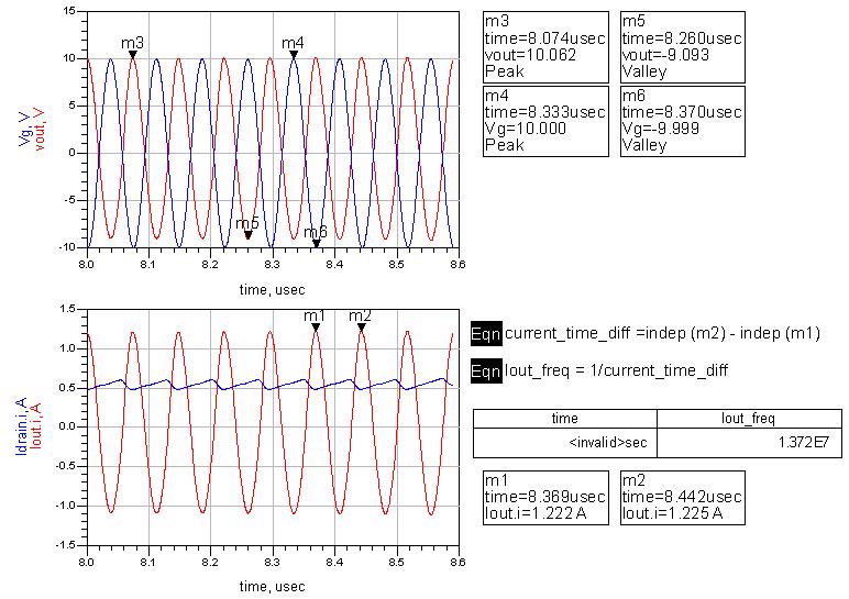
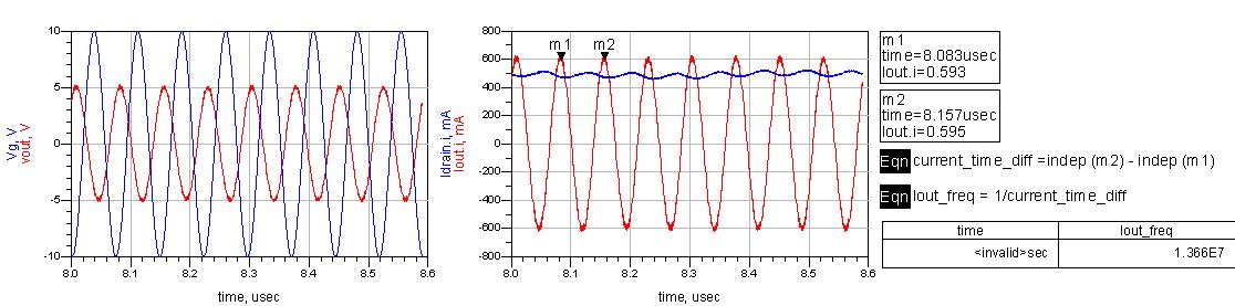
could you interpret anything from the output graph?
---------- Post added at 08:22 ---------- Previous post was at 07:07 ----------
the input is at Vg and the output should be Vout as tagged at the wire right?
Voltage gain of amplifier should be taken as Vout/Vg
Looks fine for me. Try to plot efficiency vs C8 capacitor value to find the optimized one, keeping the output power.
but vfone, the vout is actually half of the Vin ( which is Vg)... i've attached another tuned circuit..
btw which industry are you in?
---------- Post added at 12:03 ---------- Previous post was at 11:58 ----------
hi, this is the tuned result.. is it correct?
Somehow the Vout is almost same as Vin (which is the Vg)