Filter opamp in IF demodulators
Please have a look at this datasheet: it's a typical IF demodulator - or at least I saw several ICs almost identical.
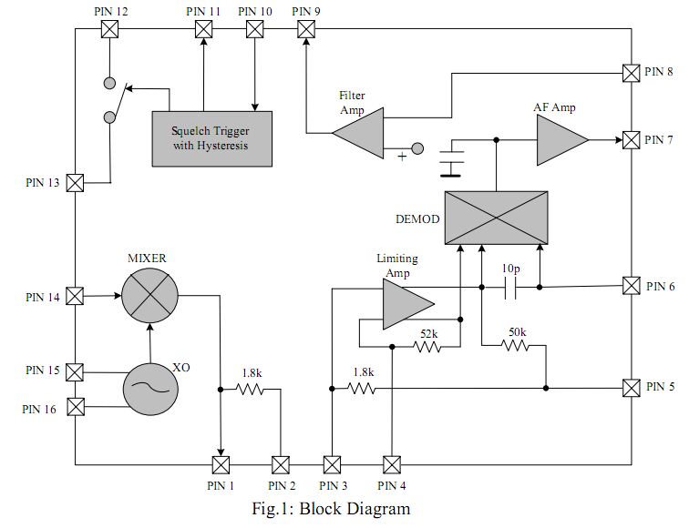
The filter opamp has only two pins accessible from outside. The positive input is always drawn as "floating". I think there is an interaction between positive input of the filter opamp and the AF amp output (demodulated audio), but I was unable to find more information on the datasheet.
Does anyone can explain me the internal connection of positive input, or lead me towards the right direction?
Thanks
Giuseppe
Giuseppe,
A part number would be handy!
Keith
Here we are... the device shown is a Siccom SRT3300, equivalent to DBL5018. You can find online the DBL datasheet, but it is not informative at all (from this point of view)
Giuseppe
It isn't. It's shown connected to a reference voltage respectively a virtual ground. So it can be expected to work in a usual inverted OP circuit. But I'm rather sure, that a complete datasheet would also specify the reference voltage, output voltage range, OP input impedance and gain.
This is the problem indeed... for both models, this is all I was able to find.
Anyway, your suggestion is useful nonetheless. I supposed there was some internal (and not shown) connection to the audio output. Possibly my assumption is wrong, and this is, in facts, simply a "courtesy opamp" with the sole purpose of designing a filter with no need for extra ICs.