Stereo and mono plug issues when connecting MIC connector and signal generator
I working on this project which I am using a transceiver to transmit analog signals generated from the signal generator. I am planning to use the external MIC connector to connect the signal generator to it with the help of a stereo plug cable with the other end as a pair of crocodile clips to clip to the signal generator. But the external MIC connector is meant for stereo plug cables. So my question is to ask what should I do with the extra third cable of the stereo plug cable cause my signal generator only require two cables (for the signal and ground)?
Thanks
Regards
There are different mic connector pin mappings in use, either stereo with two inputs, or mono, with the ring carrying a DC supply only.
In case of the stero input, why not connecting both channels to the generator?
What u mean is that I should both the L and R channel to the same signal generated?
Yes, why not?
But I read from the manual that states the middle connector (in between the 2 rings), there is a 3V power generated from its internal 3V line. So if still pump in an signal with a certain amplitude, won't it sort of clashes with the 3V?
Don't connect the signal to the ring with the voltage, use a multimeter to measure any dc in the input cable if you want to be sure.
If you have the manual then it should be clear where you should connect your input and as FvM said you can connect the same signal to both input assuming you have a stereo input.
Alex
Hi Alex, thanks for ur advice. The diagram in the manual states for connection with a terminal node controller which I am going to be using for my final product. Yes it states the 3V coming out from the MIC female connector but it didn't state where to connect it to. So I was actually thinking should I ground that 3V instead since I may not use it.
hey guys
..... its a mic connector on a transceiver radio .... its unlikely to be stereo ! :)
there is most likely to be
1 .... mic line
2 .... ground/common line
3 .... PTT line (Pust to talk)
O.P. 'er you need to decide how you are going to use that PTT line in the external mic connector to put the transceiver in TX mode :)
it would also help if you told us what model of transceiver it is so we could look up the pin connections
Also that level you input from the sig gen needs to be VERY low level a few 10's of mV
as the transceiver will have a sensitive mic preamp inside it
Dave
Hi Dave,
I was initially thinking it will be mono too. But when I look at the MIC controller function on my manual, it states "For connection of the optional external microphone (2k ohms) with a 2.5 diameter stereo plug". So it means that I should use the stereo plug right?
The PTT line if I am not wrong, I should be connecting the same channel that I am using for my signal generator.
Regards
Yes its a stereo plug, but thats just stereo plug as in 3 terminals, NOT .... Left, Right and Gnd
see my previous post comments
The PTT line will connect to GND to make the radio go into transmit
Many newer radios have a quad terminal 3.5mm connector
... mic line
... PTT line
... Data line ( for microphones that have up/down scanning buttions or keypad for freq entry)
... Gnd
You still havent told me the make of the radio ! :)
Dave
ohhhh ... You CANNOT plug a Mono plug into that socket it will short out terminals that shouldnt be shorted out You MUST use a stereo plug
Ya the model is the Alinco DJ-S45E transceiver.
Regards
ok now we know what is going on :) thanks for the file.
As you can see you have 2 plugs a mono and a stereo. the mono is just for the signal to the speaker in the speaker mic
forget about that one as you are just transmitting on that radio
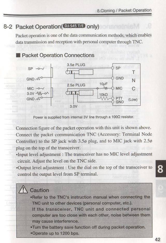
The stereo plug is carrying your PTT and mic line and that 3V line, Im wondering if that 3V rail is used for a supply for the electric condenser insert. but this pic you posted is for a TNC (terminal node controller = packet radio modem)
wonder if you can post the mic connections image as well please ? just to confirm normal mic connection
Dave
The manual didn't provide the connection diagram to the external microphone. The only other diagram they provide is the schmatic diagram but I don't think it helps, but I will just attach it here (the red circle is the input MIC female connector)
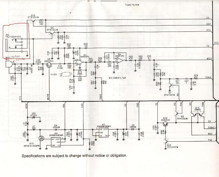
So right now I want to test with the signal generator connected to this stereo plug, should I just leave the 3V line unconnected to anything?
OK no prob, I was curious to see where the 3V line went to. Yes for your activity, the 3V line isnt needed. so the output from the sig gen goes to the Tip and the Sleeve terminals of a stereo plug (to state the obvious :) the sleeve is the gnd and should go to the gnd terminal of the generator output.
Dont forget what I said a few posts ago ..... the level from the generator should prob be less than 100mV, else it will overdrive the mic preamp and cause a distorted signal
cheers
Dave
Okay thanks a lot! :) I am planning to use 50mV in series with a 2k Ohms resistor just in case anything happens.
no probs :)
or you could just use a 5k trimpot, that would then give you some on the spot adjustment, without having to unsolder/solder in various resistor till you found the correct value. Much easier :)
report back and let us know how you got on
Dave
Okay sure. I will do the testing next week when I am back in lab. :)
Hi everyone,
I was able to transmit the signal in the wireless channel successfully. I have connected the signal generator (50 mV and 2.4 kHz) to a 1800 Ohms resistor and after which to the stereo plug cable. For the 3V cable of the stereo plug I have left it unconnected. And when I switched on the signal generator, the transmitting transceiver was able to send without me pressing the PTT button.
At the receiving transceiver, there was a little noise added to the signal maybe due to the noise in the air medium. But the signal was quite obvious.
Regards.
Hi again,
The other time I managed to successfully transmit the signal from:
Signal Generator -> Transmitter transceiver -> Wireless channel -> Receiving transceiver -> oscilloscope
Now my next step is to include the modulator & demodulator into the test setup, like:
Signal Generator -> Modulator -> Transmitter transceiver -> Wireless channel -> Receiving transceiver -> demodulator -> oscilloscope
But the problem now I am facing is that the output signal amplitude from the modulator is still quite high (I am using the MX614P IC, as such the output level amplitude is more or less constant). So I was thinking of using this MCP602 dual op-amps IC to actually attenuate the output signal amplitude like the connection shown in the below diagram.
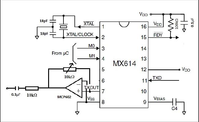
The MX614P IC main function is to convert a binary '1' to a 1200Hz and a binary '0' to a 2200Hz. So when I input a square wave into the modulator, I should get alternate frequencies of 1200Hz and 2200Hz. So I used the 10k ohms potentiometer to actually decrease the output signal amplitude to around 50mV. But the problem now is that when I decreased the amplitude to a certain value, my sine wave of alternate frequencies would become just a sine wave with one frequency. I wonder is it because of my connection of the MCP602 that is causing the problem? And one more question, what is the power handling of a typical 10k ohms potentiometer? Thanks.
In the schematic you have posted, the output from the 602 OpAmp is being returned to the INPUT of that OpAmp via the variable resistor. (That would amplify the signal, not attenuate it!).
Of course, it can't actually amplify the signal because the output impedance of the Modulator will be low enough to prevent the positive feedback from adding to it until you turned the potentiometer all the way down to zero ohms.
Anyway, in the correct circuit, you would connect the output of the Modulator to one end of the variable potentiometer and ground to the other end. Then take the variable connection and use that as the output signal. You probably don't need to follow that with an OpAmp but if you did, it would have zero gain (output connected to non-inverting input) and you would only use the OpAmp if you needed to provide a low impedance source to the next stage of your project.
The power handling of a potentiometer depends on the manufacturer's specification. It its small, then you shouldn't expect it to dissipate more than a few milliwatts, which is enough for your project.