Ads Layout Component erroneous impedance simulation
时间:04-07
整理:3721RD
点击:
Hello,
I created a layout component in ADS.
at 450MHz I simulated the input impedance for two different resistance values placed between two ports.
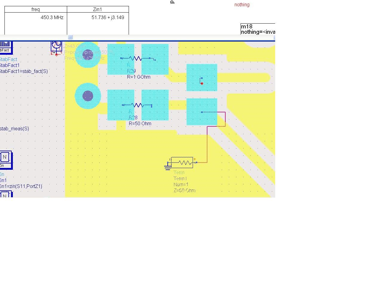
Using a 50 ohm resistor I measured roughly 50 ohms.
Using a large resistor I measured roughly a short.
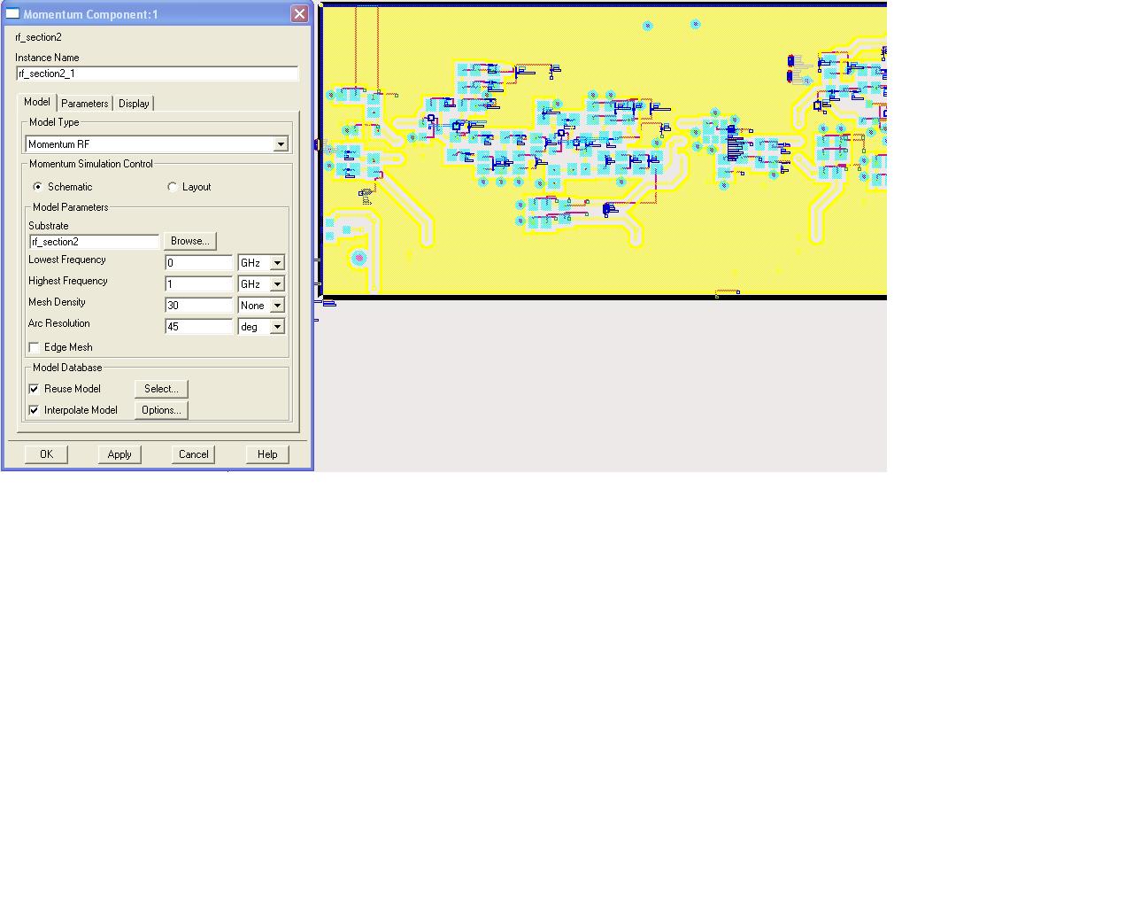
My mesh setup is attached.
Can anyone explain why ADS is giving these incorrect values and how I can fix the problem?
Thankyou
---------- Post added at 05:13 ---------- Previous post was at 05:09 ----------
See below
I created a layout component in ADS.
at 450MHz I simulated the input impedance for two different resistance values placed between two ports.
Using a 50 ohm resistor I measured roughly 50 ohms.
Using a large resistor I measured roughly a short.
My mesh setup is attached.
Can anyone explain why ADS is giving these incorrect values and how I can fix the problem?
Thankyou
---------- Post added at 05:13 ---------- Previous post was at 05:09 ----------
See below
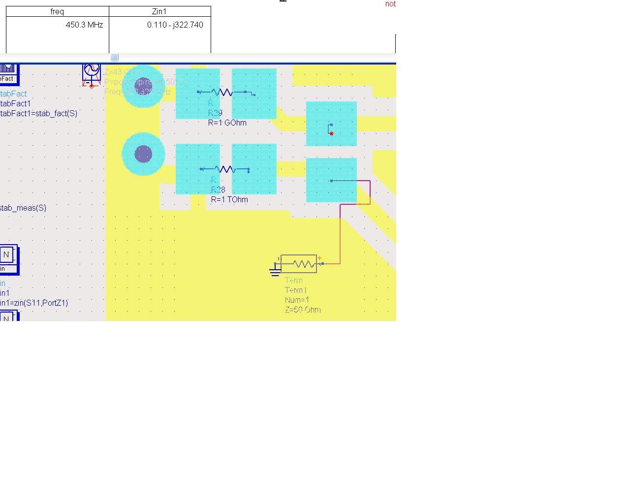
0.1-j300 is close to an open circuit, not a short. Plot it on a smith chart, you'll see the open.
Your simulation seems fine.
Mazz
Why do I not see a Large resistance value with a small amount of inductance. I would have expected a value similar to 1Tohm + 3.149i; Instead 0.1 - 300*i which has a really small real component with a small series capacitor.
I'm not able to tell you exactly why.
But, looking at your layout, you are adding in shunt to the high real load an open stub (from some calculation, 15mm of 50 Ohm impedance line (in air) terminated by an open will give you exactly that impedance). This is the answer, I guess.
I hope it can help.
Mazz