Confusion of S11 definition
In a two port network, S11 = b1/a1 when a2 = 0, which means the load side acheives impedance matching.
But when I measure S11 with a network analyzer, S22 is poor, does this means the measured S11 is not correct since the load side is not matching?
How to assure that a2 = 0 in a S11 measure/simulation?
a2 is pretty much assured of being = 0 since your device is attached to a good 50 ohm characteristic impedance transmission line that is terminated in a very good 50 ohm load. By definition, any wave travelling down such a line will not reflect back.
The assumption in all this is that your device is connected well, with few parasitics, at its output port to a good 50 ohm line. If you have a broken test fixture where the port two connect has an open circuit, for instance, all bets are off.
biff44, thanks for ur reply, it's very helpful.
In measurement, I know that a cable with 50 ohm characteristic impedance can be connected between the DUT and instrument. But what will happen if there is only a 50 ohm termination without cable, eg., in doing an SP simulation. (S-parameters without transmission line can be described by power wave instead of transmission wave, am I right?)
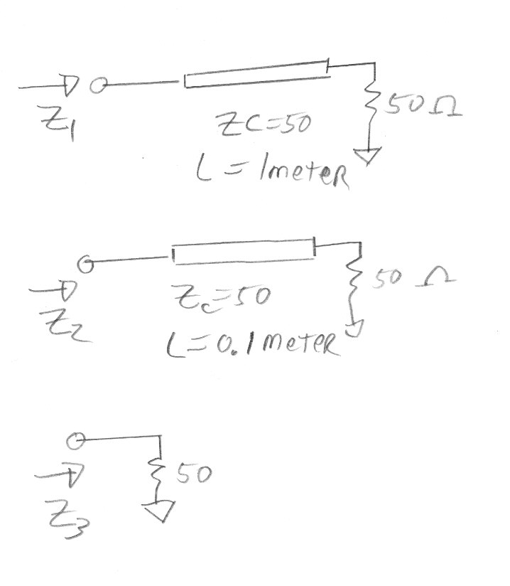
I does not matter where the load is. A picture is worth a thousand words, Z1=Z2=Z3=50 ohms:

So if there is no reflection from the Z1 load, and Z3 has the same impedance...must be the same effect!
In a modern network analyzer, the small deviations from an ideal load are corrected for with your "calibration routine", where you measure known good items and the network analyzer figures out the small deviations from ideal in the measurement system.
Rich
