Realizing a capacitor by TL
Can anyone please advice what is the best way to substitute a capacitor by Transmission line at 40 GHz?
A gap in TL, coupled lines?
Thanks in advance
A capacitor has insertion loss less than 1dB, but gap or coupled lines have insertion loss more than 15dB if the gap is about 0.15mm, you can simulate it.
AMC, Muruta have microwave capacitors whose SRF is more than 40GHz.
Another way is using waveguide coaxial converter to replace capacitor if you have enough space.
No. Finger structures (interdigital capacitors) can be used and work fine.
Thank you all specially Tony!
The problem with Tony's answer is that it is wrong.
Volker: I do not know about how much the insertion loss diff is (as per Tony) but the fact that cap (lumped ) exist at 40 GHz helped.
Yes, you might find lumped microwave capacitors.
Personally, I would avoid a lumped capactor with all the related problem at these frequencies. The "printed" capacitors are much easier to design & use. They perform perfectly fine with insertion loss < 0.3dB or so.
thank for volker's idea, I would simulate it .
Volker: Could you post some links about designing printed capacitors the one which you are recommending?
You might find some software specific application notes like this: http://cp.literature.agilent.com/lit...989-8912EN.pdf
Here is how I designed my 24GHz ICAPs:
Try 1 and 2 finger pairs, with a gap at the minimum design rule limit and line length ~lambda/4. Simulate that, check if you better use 1 or 2 fingers and check the effect of the finger width. For the gap width, smaller should be better, but you can easily check that.
When I did my 24GHz designs more than ten years ago, circuit simulator models where not very accurate for ICAP models with lambda/4 line length, so I recommend using an EM simulator. Something simple like the free Sonnet Lite student version will do. Or if you want to stay within the model circuit simulator, better use coupled line model rather than ICAP model.
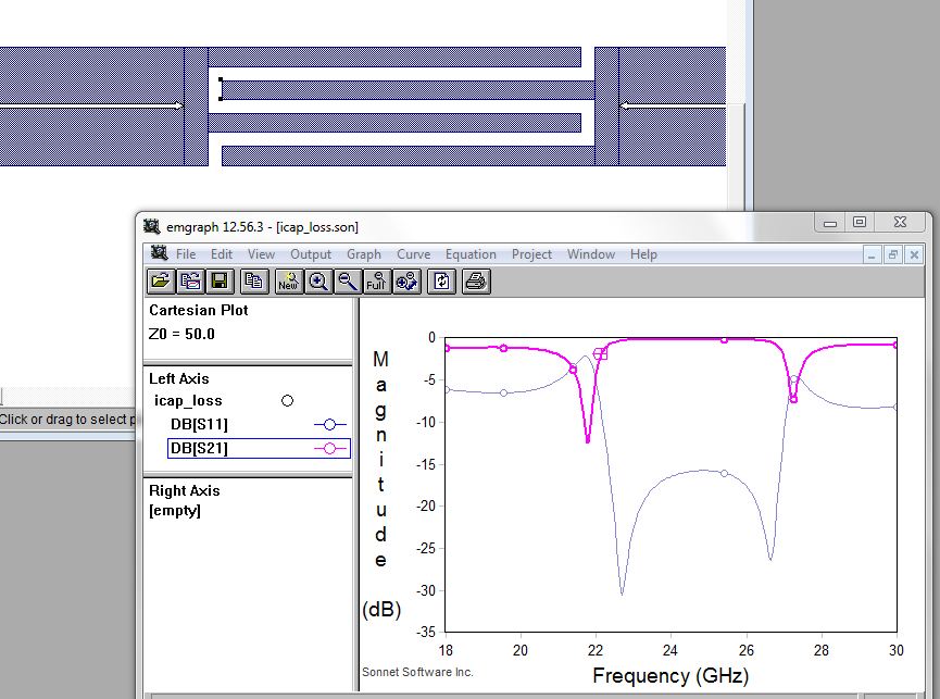
This is not my actual design, but a simple example to give you an idea. The actual design had just one finger pair, so you might call it a coupler rather than an ICAP.
- Realizing a J-inverter around 350 MHz
- How the output power changes by varying the capacitor connected in series with gate
- DC blocking capacitors or interdigital capacitors at 24 GHz
- Why do company sites have inductors and capacitors in an s2p file format?
- DC block connector vs capacitor
- How to choose the right capacitor?