DC block connector vs capacitor
The DC block connector available from various manufacturers such as http://weinschel.apitech.com/weinsch...wmod7006-1.pdf support a particular frequency range. My question is why can't a capacitor with appropriate matching can be used instead of these DC block connectors?
How are these DC block connector made? Can someone point to a schematic?
Thanks
The schematic is shown in the datasheet.
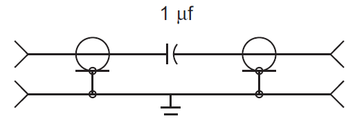
The interesting point is how the capacitor is built into the coaxial transmission line achieving low SWR over the full frequency range. That's a matter of capacitor RF parameters and transmission line geometry.
Hi FvM,
So the capacitor is realized using coaxial lines. There is no physical SMD like capacitor. Is there a reference where such a coaxial transmission line design is carried out which I can refer?
Thanks
That's not what FvM stated. The capacitor in the link is inside a coaxial connector. Essentially it is a connector that passes RF but blocks DC. Almost certainly in view of the frequency range it uses some kind of disc capacitor with a connection on opposite faces to minimize inductance. So the capacitor itself isn't fabricated using coaxial lines, it is wired in series with coaxial lines inside the body of the connector as shown in the schematic.
The frequency range is decided by the capacitor geometry and dielectric, lower frequency ranges will use larger values but construction may impose an upper frequency limit. Higher frequency ones will use a lower value, probably optimized for minimum inductance.
Brian.
For 1 μF/50V I would expect a small MLCC mounted in a coaxial transmission line structure. Shape of inner and outer conductor varied for minimal SWR.
Typically I use a simple ceramic capacitor for DC block, but hey, it is all about the frequency range necessary and the alowable series inductance.
I recommend to use quarter-wave coupled lines DC block. With modern PCB manufacturing it is easy to obtain good coupling (thin lines with a very narrow gap). For wider bandwidth H-slot transitions may provide good S21 over few GHz bandwidth, but it requires three layers of copper: layer1-microstrip1, layer2-ground with H-slot,layer3-microstrip2. I would consider connector from your link only for some measurement purposes, mainly to protect expensive equipment input ports.
Thanks all for the comments. It is a capacitor embedded in a coaxial line tuned for low SWR.