approperiiate substrate
I,m going to design some Wilkinson power divider for frequency Band 900-2450 MHz.I'm going to design on FR4.Is this substrate appropriate for my frequency band.I can design on both 8mm and 16 mm laminates.which one id better?
thanks in advance
Hi
This depends on how you realize your design. If it is distributed(transmission) or lumped?
Lumped design I think it would be OK, distributed depends on how much loss you can tolerate because you need to do a broadband design...more transmission lines
Regards
thanks for your reply
of course in my design I can compensate the losses using amplifier.my main doubt is about
the similarity of simulation and practical implementation in my frequency.and another point that I have to
point out is that i'm going to design microstripe power divider.
thanks in advance
FR4 loss is high I think it's tg loss is about 0.02 and I donot recommend it.
In fact FR4 is not very suitable for precise or in otherwords dimension dependedent applications.Because er is varibale by manufacturer and its thermal stability is not good enough.
It can be used for non precise applications such as application boards etc. If there are microstrip lines,lange couplers,wilkinson dividers,microstip filters and other circuits where the dimensions are very strict, it shouldn't be used..
Do you really mean to say 8 or 16 mm? That is really thick.
Assuming that you know that FR4 is a poor substrate for microwaves, I would use 1 or 1.5 mm thick board.
what is your power specification? is it very high power so that you use so think substrate?
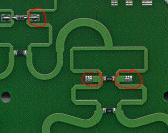
Many years ago, we designed a 1 to 8 divider on FR4 for the frequency range 900MHz to 2.1GHz. The design had an amplifier on board, for a total insertion loss of 0db from input to each output, so it was no problem to compensate the extra insertion loss at higher frequencies.
The variation of epsilon between the prototype material and the final production units was a problem: we had to tune the dividers (tuning patches) to meet the 25dB output isolation spec.
You mean 0.8mm or 1.6mm? We used 1.6mm, which resulted in reasonable line width.
thanks for your helpful replies
I apologize for my wrong data.Yes I meant 0.8 or 1.6 mm.
The idea of volker is very close to what I kept in my mind.would you please tell me more about
your tuning patch Idea.I will be appreciated
With the circuit simulator, we had identified places where the output isolation can be tuned by extra capacitance to ground. In the layout, we added small copper segments that could be connected as needed, to add that shunt capacitance.
approperiiate substrate 相关文章:
- Antenna design with 'Air Substrate'
- Ceramic or High K PTFE Substrate
- How to mount RF substrate into a Al housing for making an RF module
- best MS substrate to use in a wireless energy harvesting (rectenna)
- Substrate to substrate interconnect between two CPW substrates
- How to choose the substrate's thickness for a 9.35Ghz application