PLL with fine frequency resolution
I have to design a circuit to realize a frequency voltage converter around 400 KHz (bandwidth of few hundreds of kHz) and with a resolution of at least 1 Hz. I am thinking to use a PLL but I am not sure that I can get that frequency resolution. Can you please suggest me one in order to get that performance?
Many thanks, I don?t have experience with different kinds of PLL
Luca
I wouldn't use a pll for this, I don't think you can get the required accuracy. You are looking for 19-bits of resolution (.00025%), that sounds pretty tight. I would look at some type of arrangement of enabling a counter for a fixed time, allowing your input to increment the counter, and apply the counter output to a DAC.
Many thanks for answering to me. I have already realized a reciprocal frequency counter to get a resolution of 0.1 Hz and it works well. However, with that technique, I don’t manage to follow a fast variation of input signal and I am limited to quite static applications.I look forward to hearing from you.
Luca
Maybe you should explain what you mean by "frequency voltage converter".
A frequency to voltage converter will take a signal (typically a square wave) and convert it directly to a dc voltage. 1 hz resolution is therefore meaningless. The output is in volts, not hz.
I think what he means is that he needs to be able to resolve the difference, e.g., between 400 Hz and 401Hz. If he's using the aforementioned counter method, this does have meaning. This is no different than saying "I need 1mV resolution" for an ADC system, where the output is in bits, not mV.
---------- Post added at 18:11 ---------- Previous post was at 18:04 ----------
Luca,
Yes, that's one drawback of that counter method. Here's another method I've used which may work for you: On the first rising edge of input signal, enable a counter that is incremented by a high-speed clock. Count N samples of the input signal and then stop the counter. The value in the counter is now proportional to the period of the input signal. I've implemented this method in an FPGA, I'm not sure if you have that available for this project.
If you're trying to measure the frequency of a signal with bandwidth close to the frequency of the signal itself, then period measurement isn't even really valid, since your signal's "frequency" can change greatly within one fundamental period. The counter method will just give you an estimate of the average frequency over one period, which will reduce your measurement bandwidth.
Of course you need to know how quickly the input frequency is changing. The counter method assumes a 'static' frequency.
Based on my experiments a PLL will be in synch with your incoming signal for a while.
Then the waveforms will grow out of synch. If the freq difference is a few Hz then it will take a few seconds to get out of sync.
The PLL will probably keep its own time rather than shifting its phase to match yours.
I think the output of the PLL will be a slow square wave which changes state every few seconds.
Don't know if this will help you in what you're trying to do.
To be honest, I do not know what he means, and tire of having to read peoples minds. I can think of a couple easy ways to do such a measurement, but am waiting for a better definition of the problem.
A Fractional PLL will serve for this purpose..
I have a resonant accelerometer where the sensing is realized by analyzing the resonance frequency of a MEMS device. My input signal is a square wave around 400 KHz and I want to measure the change in it with an accuracy of 1Hz (I would like to distinguish 400000Hz from 400001 Hz). A classic frequency counter unfortunately is not a possible solution because is too slow to detect fast change of my input signal (it would be fantastic to manage to detect variation of input signal with a bandwidth of few hundreds of Hz)
Many thanks for trying to help me
Luca
Okay, before you said the bandwidth was hundreds of KHz, now it's hundreds of Hz? Big difference.
Here's what info you should have to start: desired bandwidth, slew rate, and maximum range of acceleration measurement. Also you should specify what kind of settling time you want to a given error (in frequency or LSB or whatever). And tell us roughly the relationship between acceleration and frequency, so we can translate those physical specs to frequency measurement specs.
If possible, you should try and increase the resonant frequency of the structure as much as possible without sacrificing too much Q. That makes high bandwidth measurements easier.
I would make an analog quadrature frequency discrimintor, using a high Q phase shift network, and measure the voltage at Vout. I would trim it so that at 400 KHz to output voltage is 0V, and +/- deviation in frequency gave me a +/- deviation in output voltage.
If you want to get fancy or more precise, you could replace the phase shift network with a 400 KHz crystal or ceramic resonator.
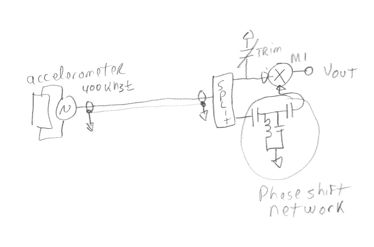
M1 is a low frequency mixer with a DC coupled IF output.
Thanks to everyone.
For Mtview,
When I wrote in my first massage a bandwidth of few hundreds of kHz I was talking about the sensitivity range of my circuit (I need to measure the resonance
frequency of my MEMS oscillator in the frequency range 400Kz +- around 10%, but I think 40 KHz could be fine). Instead, in my last message, I was talking about the wideband of sensor, I meant the fastest frequency variation during the temporal acquisition that the circuit can detect.
Luca
fine PLL resolution 相关文章:
- How to define excitation and boundary condition of a dual and quad output switch?
- Infineon's BGT24MTR11 "IF 1/f corner frequency" is limiting FSK modulation frequency?
- Infineon BGT24MTR11 mmic: should RF in/outs be decoupled from ground?
- port refinement hf3d error too few conductors were found on port 1
- define discrete capacitance in cst
- Ethernet (Profinet) to rs232 and vise versa