Inductor characterisation in Cadence
I have recently switched over from Mentor to Cadence.
As such I am having problems with characterising a spiral inductor.
Basically I want to characterise its Q, Rs and L values over various sweeps (frequencies, dimensions).
I believe the way to go about doing this is through sp analysis. This I have done by placing two ports
either side of the inductor and sweeping frequency. However, the resulting answers dont look right.
My questions are:
1. Do I really need sp analysis to get Q, Rs and L? If so, can some please give me a guide of how to do this correctly?
2. Can I get the above parameters through ac analysis? Tried this by placing an ac source across the inductor but my
resulting values dont look correct.
Any advice would be greatly appreciated.
Thanks in advance,
Diarmuid
Maybe it is not a simple way, but normally, similar case for me, I will use cadence allegro complete layout, then import spiral model into HFSS for 3D EM analysis, then optimization lump-model in ADS based on HFSS results.
I assume that you use an inductor from the library, with existing electrical model, and do not you want to EM analzye your own inductor layout?
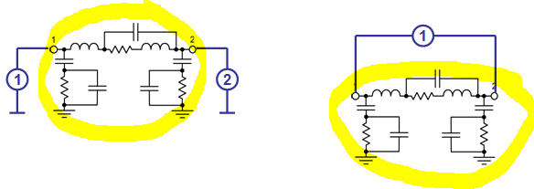
For calculating effective L and Q, you can connect the ports in different ways, as shown below. This depends on the use of the inductor in the circuit. If you use the setup on the right side (purely differential, floating substrate) you will get a higher Q for the same inductor. If you want to allow shunt path to the substrate, use the left setup.
Hello,
Thanks for the quick response.
What I did in the end was ground one terminal of the inductor and connect the other to a port. Then running sp analysis I extracted the Z11 parameter and got Q and L from there. This
was the procedure followed in the accompanying process document which outputted similar Q, L curves to me.
The inductor will be used in an LC-tank. Does the above characterisation agree with what the inductor will actually see in practise?
I now need to characterise the varactor configuration. As it will be two AMOS varactors connected gate to gate with their bulks at the tank, I presume
I must do a 2port sp analysis. Is this correct? If so, do I just connect a port to either side of the varactor configuration and proceed with sp analysis from there?
Thanks in advance for any help.
All the best,
Diarmuid
Hello,
my work is inductor EM analysis with Sonnet, so I can not help you with the detailed setup in Cadence. From the equivalent circuit models you can see that shorting one side of the inductor to ground will short some of the substrate loss. I think that the left setup (ports on both side of the inductor) is more realisitic.
Equations used when I evaluate these 2-port configurations in Sonnet EM:
Q = mag( imag( Y11 ) / real( Y11 ) )
L = - imag( 1 / Y21 ) / ( TWO_PI * FREQ )
Hello Volker,
You seem to know things quite well. Therefore, I have detailed my problem a little more in the thread "LC tank characterisation".
Here I have included diagrams to clearly show my situation.
If you could take a minute or two to look at that it would be most helpful.
Thanks and all the best,
Diarmuid
Inductor characterisation Cadence 相关文章:
- Distance between air coil inductors
- How is the maximum inductor value in a technology process is determined
- Transmission Line vs Lumped Inductor Choice in Distributed power Amplifier Design
- Why the inductor equation is different in this paper
- Why an input inductor required in all GPS LNA?
- How to realize inductor from transmission line (micro-strip and CPW lines)