FET Colpitts Oscillator (Microwave)
I've building a 430Mhz Transmitter for microwave. And for some strange reason i couldn't get any output frequency from my circuit. I've checked many things i could check including the design, and i still could get it to work. The design i'm currently using is a proven design that has been used and tested over the years, but the problem is my first stage, which is Fet Colpitts Oscillator was designed to work around 115Mhz including 115Mhz Quartz oscillator providing the stability.
1. My question is, can this circuit still works with another Quartz Oscillator of 216 Mhz, without redesigning the Biasing network around the quartz, as shown in the attached diagram? In addition Will the 216mHZ quartz Oscillator change the output to 216Mhz rather than 115Mhz originally designed.
Please any help will be appreaciated.
P.s I'm a Student.
Frequency of oscillation is determined by the sum interaction of all components in the control network.
No component can be allowed to stagnate.
Each component must charge via the current available to it. Stagnation is prone to happen if a resistor is too small, or a coil value is too small, or a capacitor value is too large.
Generally speaking, if you want a higher frequency, reduce values of the coils and capacitors. Leave resistor values the same.
A circuit lacking a crystal will oscillate at a rate determined primarily by the coils and capacitors. Secondarily by the resistors.
Oscillation occurs when you have sufficient voltage/current swing going on at the transistor bias. To reach this point you must first apply sufficient DC bias to turn on the transistor slightly. Usually 0.6 V. You're using a FET so you must modify to suit.
An FET is normally operated as a voltage-controlled device. Is the bias carrying current? If not then is there a current path for the interaction of coils and capacitors? This may be crucial to proper operation.
As to adjusting the oscillation frequency upward, if you want to obtain twice the frequency, you divide all coil and capacitor values by 2. This applies only to components in the control network.
What components make up the control network? Your schematic is not clear enough to make out, but you can locate a few strategic points to attach an oscilloscope, and watch for at least a few oscillations after you power up the circuit. By tweaking a component or two you might get better performance.
Change your circuit with the one attached (minor changes) and it will work.
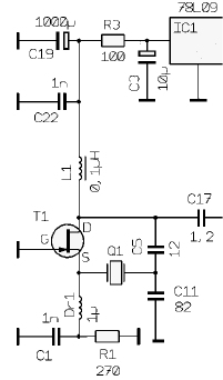
I doubt, that the oscillator will work for an overtone crystal without additional selection means, like the parallel inductor in the original circuit. Generally, a LC tank is more relibale for overtone.
The inductor parallel to the crystal is the reason not oscillating at higher frequency.
The posted schematic is an working 175MHz overtone oscillator. May need some tuning to get 216MHz, but may not.
The choke DR1 makes less RF voltage drop at the source point.
Wow! Thanks for all your reply.
Hi Vfone, please how can i get the proposes Circuit tuned to 216 Mhz? The problem is, i don't have any simulation to test the circuit so that's why i'm asking about proven design.
obviously, 78L09 output is +9V.