Re: SA602 colpitts oscillator help needed
@ -30 dBm
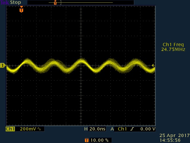
@ -20 dBm

@ -10 dBm
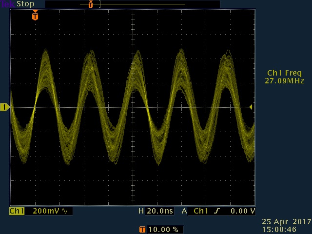
At -20 dBm the output should be pretty clean if overdriving was the main issue, isn't it? Below -30 dBm the output quickly vanished.
P.S.: It is not fixed frequency but a band about 500 kHz wide
If your scope support FFT or you can view the output on an SA, look at which point, the 3rd order products start to become significant.
Maybe it was not practical to use said signal generator because the signal distorts badly at the input as I found out afterwards. This is probably an impedance mismatch effect but I didn't have a matching device at hand to find out. The signal (at the input) looked pretty similar to the output signal you can see below. Therefore I was unfortunately not able to do what you suggested and hooked it up to the vco buffer amp again.
The input signal to the mixer:
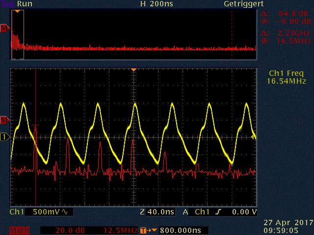
The crystal oscillator:

The final output signal:
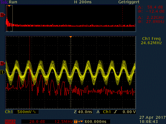
I think the input signal is not clean enough, right? This would mean that I need to have some LP filtering going on somewhere, most likely around the buffer amp:
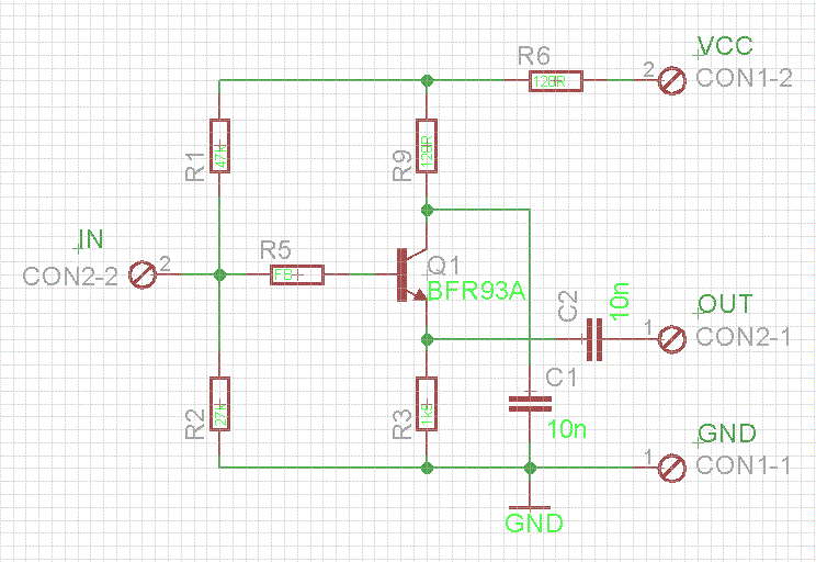
What would be an elegant way to do it? And will this be the only suspect right now or is it maybe just part of the problem?
How do you measure the oscillations ? You're using a scope probe ? Pay attention, small fraction of scope probe capacitance will disturb the oscillator.
Yes, I do and I'm basically aware that it can cause trouble but the alternatives are limited. Maybe you or someone else can suggest a better way? As long as it doesn't involve buying additional big-bucks equipment suggestions are certainly welcome
My scope does support active probes but so far I don't have any. Maybe a Tek P6205 FET probe (which is supported) might be worth a consideration. These have 2 puff capacitance compared to 14 of the probe actually used. But I haven't used any such probes, do they actually make a world of difference for such an application?
You don't have to use expensive FET probe in order to just observe the oscillations.If the measurement accuracy is not your concern, you can connect a 100k axial resistor to live pin of the probe to decrease the charging capacitor.( it's just to surveillance )
Thanks for this input, I was able to observe a difference when using the resistor method; however 100k were too much so I used 10k.
In the meantime I have also changed my VCO topology for a fixed inductor/variable capacitor one so there may also be some coincidental differences from this.
Here is the input to the mixer measured without the 10k resistor:
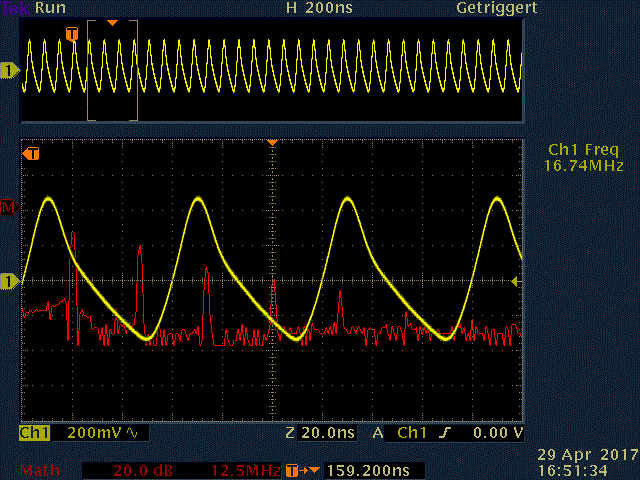
And with the 10k resistor:
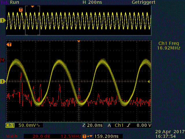
The oscillator with the resistor:
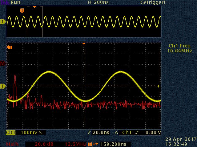
And the output without the resistor:
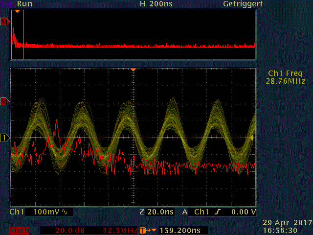
Here there was no signal with the resistor.
Unfortuately the output is still super crappy, but I'm not sure if the input is still a cause of concern. What do you think and what should I do next? I have already tried and added some attenuation at the mixer input but the output didn't look any better.
