Bandpass filter design help needed
1.
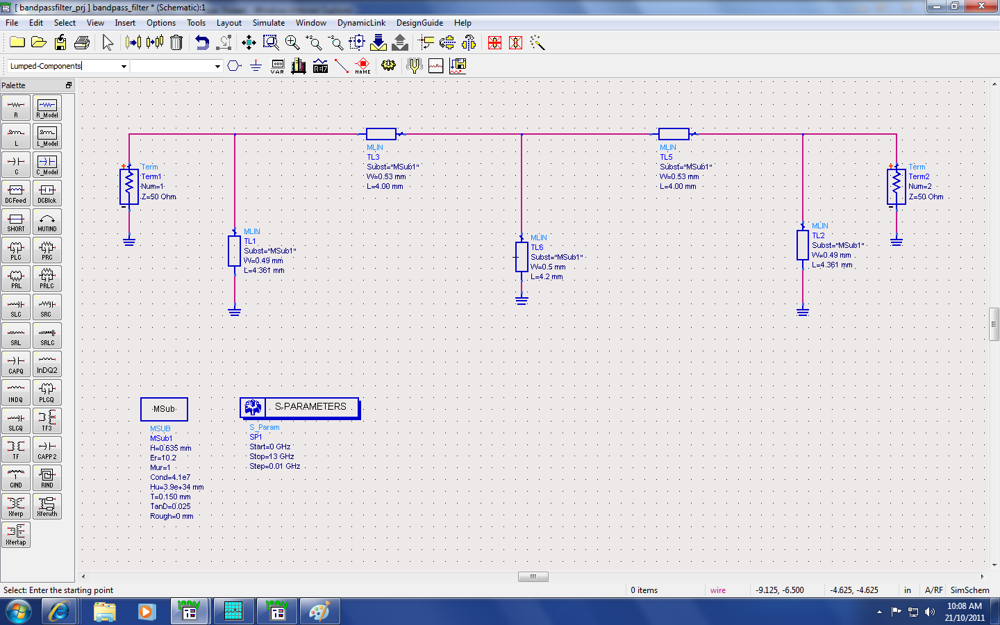
It looks like you have 5 inductors. Did you progress to this point step by step, while observing what the response graph looks like with 2 inductors, then 3, etc? (Or whatever series of steps leads up to what you have now.)
2.
Is this network an outgrowth of one with fewer components? Perhaps the values you'd use with a 3 inductor network would not necessarily work for a 5 inductor.
3.
The inductors influence each other. Hence changing one value alters the time constant seen by other components. Possibly requiring that you change their values as well?
4.
Did you set the inductor values according to a formula that is supposed to apply to all 5 in a network?
Or have you tailor-adjusted each value individually to meet a desired rolloff curve?
5.
Your specs give length and diameter. Is the simulator treating these all as single layer air core? Are these figures meant to yield a certain Q, or some other characteristic?
---------- Post added at 17:51 ---------- Previous post was at 16:45 ----------
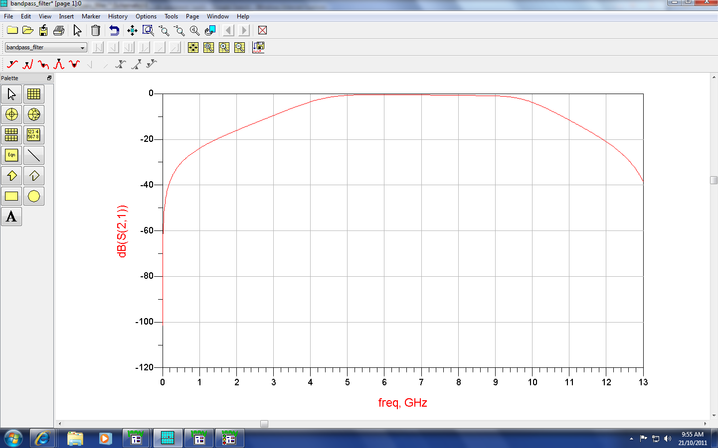
After looking at your graph again I guess you mean that the curve should start dropping immediately to either side of 6.85 Ghz. A bell shape.
Your center frequency appears okay. However you have a plateau rather than a bell.
This means the part of your network that attenuates low frequencies has too high of an overall millihenry (or microhenry) value.
And the part of the network that attenuates highs has too low a value ... I think. If it were a speaker crossover then I'd say the tweeter was getting midrange emphasis which is a sign of too high uF capacitor inline. Since you're using inductors it gets me mixed up, so switch it around whatever way is correct.
Microstrip filter can't reach so wide bandwidth, you must use special microstrip structure to do it.
You should increase the number of sections that will cost you in-band ripple and attenuation.
what kind of software that u used?
AWR is good for filter design.