Impedence match between antenna and rectifier
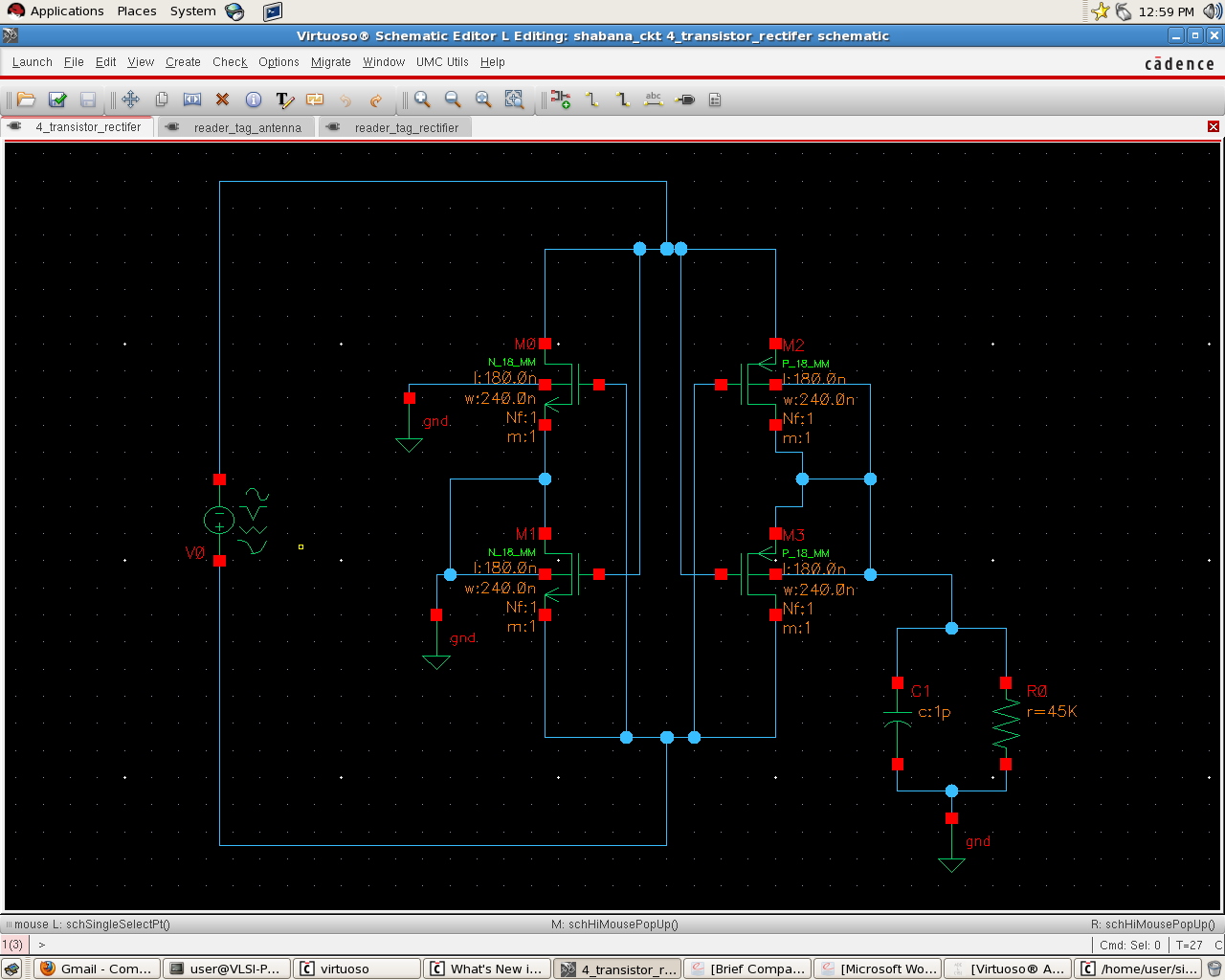
I have designed a 13.56MHz antenna for a RFID application. In addition, I have designed a 4-transistor cell MOS rectifier.
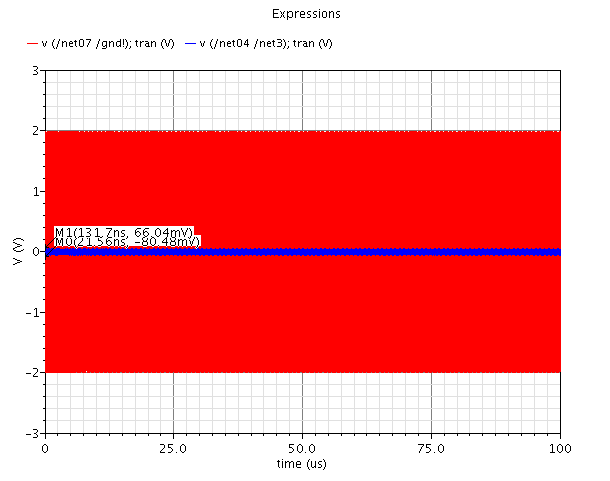
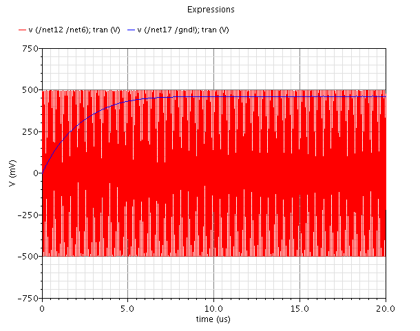
I had simulated them individually and checked the results.
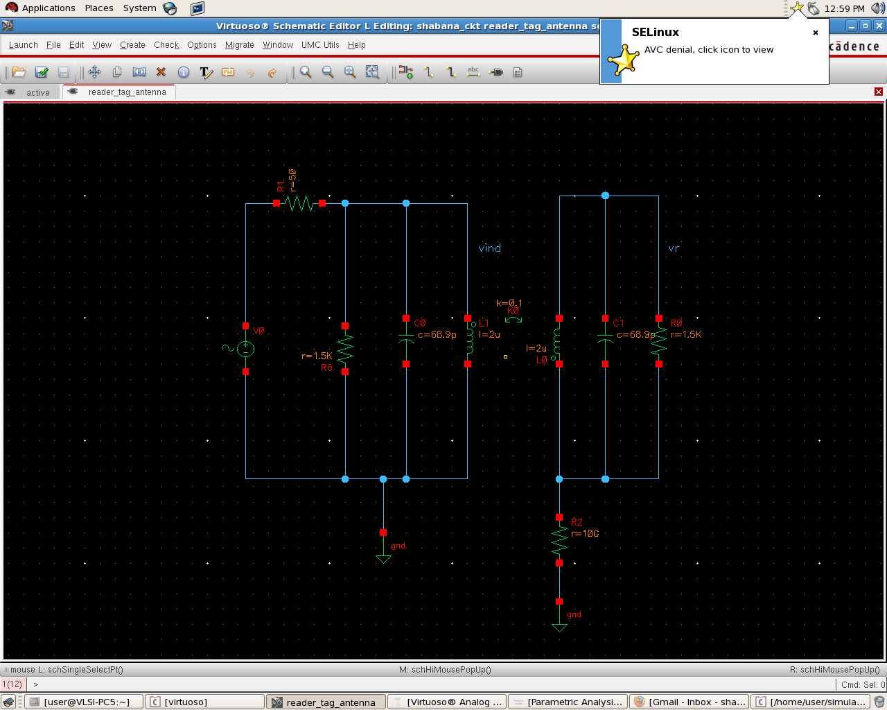
Firstly, I have given some 2V amp of RF energy to the reader antenna (Series Resonant Ckt). Using coupling, tag antenna (Parallel resonant circuit) extracts RF energy from the read antenna.
Secondly. I had designed 4 transistor cell MOS rectifier and simulated the results by giving 1v Pk-Pk as input to rectifier.
Now, my intention is to club these ideas i.e I will simulate the ckt by giving 2V as amplitude to the Reader antenna and check the rectifier output.
So, I need to do impedence matching between the tag antenna and the rectifier. For this sake, I have used 50ohm resistor. But I don't see little voltage at the rectifier output.
I have attached the circuit diagrams.
Please let me know where I am wrong.
I have included the individual simulation results.
I have changed the load resistance to 1M ohm and load cap to 200pf and obtained the attached result.
Your observation is correct. A typical detector generates a larger voltage on a high-resistance load as it rectifies the RF power.
Once you increase the DC load by reducing load resistance to 50 Ohms , the voltage drops significantly.
The problem is that your desire is to generate DC POWER by rectifying AC or RF power.
At 13 MHz, your task is relatively easy as there are many good Schottky diodes offering the fast response needed in an efficient rectifier. What you should do next is use various resistor values as DC loads, and find the best value providing the maximum efficiency (maximum DC power).
The next step is to find if you can use one diode as a single-phase rectifier, or, two diodes as two-phase rectifier. At lower frequencies, a diode quad is used in bridge rectifier for the best efficiency. The antenna you use at 13 MHz would need to find an impedance- matching network for the best efficiency.
Usually, detector diodes are characterized for low-level signals, like -20 dBm. For higher power levels, manufacturers do not offer any diode specifications; you must find them. RF impedance of your rectifier depends on the load impedance as well as on diode parameters under a high-power condition.
Do experiments and find the best results!
1) Vary your DC load to find the maximum power point of your antenna. If it is far from the impedance of your actual DC load then:
2) Vary the RF impedance of your antenna to get a better DC load impedance.
Hi SherpaDoug,
My desire is to rectify the RF power absorbed by the tag antenna.
Moreover, I want to go for ultra-low power rectifiers and my idea is to extend the same to UHF band by changing coil antennas to dipole antennas. So, I preferred four transistor cell model to schottky diodes.
I will go by your suggestion by varying the DC load and will check the performace.
Thanks!
- The shown circuit is parallel resonance
- 2 V across the coil would is a rather low driver voltage for a RFID reader. 2V input to a impedance transforming circuit would be at least a moderate drive
Impedance matching isn't the usual mode of operation for a passive 13.56 MHz tag circuit, I think. It needs to keep a certain resonator Q and a margin for load modulation. If the design is based on a standard like ISO 14443 or 15693, you should assume a tag coil voltage according to the intended coil dimensions and the standard's field strength specification.
Impedance matching will be a topic when changing to UHF RFID.
Although schottky rectifiers are an obvious solution, self-steered MOSFET rectifiers have been described in literature and can be expected with some of the existing 13.56 MHz tag chips. The reference tag circuits in the standards are using schottky diodes.
I don't remember to have seen a MOSFET rectfier for UHF tags.
Sorry FvM, I have posted wrong image. I realized after seeing your post.
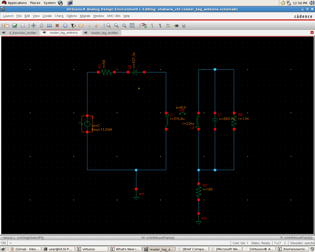
The L, C and k values in the series resonant circuit are rather strange, however.
As mentioned in my earlier post, its a big mistake to post wrong image.
I have designed series resonant circuit at the reader end and parallel resonant circuit at the tag end.
Moreover, I am keen on UHF tags but I want to see the power extraction at the tag part. So, I started with 13.56MHz as they are coil antenna's.
But your point is considered. I want to check the approximate values for time being but not the exact. I am in the initial phase of my analysis and want to check with this circuitary, what will be the power at the tag antenna and how much is the efficiency of the rectifier?
Moreover, I selected EIRP as 4W at the reader antenna end.
Please help me how to proceed with this data and analysis
I have seen some IEEE papers suggesting MOSFET rectifier for UHF tags as they are ultra low power with good efficiency
---------- Post added at 08:30 ---------- Previous post was at 08:27 ----------
I have selected K as 0.9 for max induction.
L,C values are selected depending on calculation of f= 1/2*3.14*sqrt(L*c)
k = 0.9 is unrealistical high for a RFID geometry. It won't be even achieved if the tag is directly placed on the reader.
I see c=437.3u, l=315.8u in your schematic...
Upon your suggestion, I have changed the values of L and C as 4.5uH and 30pf at the reader antenna end and L and C as 10.8mH and 150pF at the tag end.
Hope these values are feasible.
I am changing K as 0.5
What do you say?
---------- Post added at 09:05 ---------- Previous post was at 09:03 ----------
Moreover, I have considered 4W EIRP and RF input power at the reader antenna is 1W.
Since, both the circuits are in resonance, P = sq(V)/R. I have selected R as 50 ohms.
So, the voltage at the reader antenna is 7V. Is this practically possible?
Am I correct?
please correct me if I am wrong.
I have simulated the circuit using 7v as amplitude at the reader antenna end. attached is the circuit and result.
I didn't want to suggest particular values, because I don't know which setup is modelled here. I just stumbled upon the non-resonant dimensioning. As I already mentioned, the size and number of turns for the reader coils is usually chosen to achieve the specified magnetic field strength in the so-called operation volume. Tag coupling factor is then a result of tag size and distance.
Thanks for suggesting FvM. I understood your point.
I am doing this to analyse the power extraction at the tag. I am not worried about the distance at this moment as my area of interest is UHF.
Can you please let me know whether the voltage amplitude of 7V at the reader antenna side is feasible?
The ISO14443 readers design I know have reader coil voltages (achieved by series resonance) of several 10 up to 100 Vpp. For vicinity ISO 15693 with respective large "antenna" coils and several W power, they are considerably higher.
The situation is completely different at UHF frequencies, where you have matched antennas, that radiate the input power.
Thanks FvM. I tried to give input power of 1W by changing the RF input impedence from 100ohms to 1k ohms, which in turn results in changing the amplitude of the RF input of the antenna from 7v to 40V. But the power extracted by tag antenna is 100mV Pk-Pk with 0.5 as coupling coefficient. I am not sure how far my simulation and analysis is correct.
By any chance, do you send me the circuit of ISO14443 based reader/tag circuit?
Thanks