Need to modify SWR/POWER meter for lower frequency use
Workman 104 VHF/UHF SWR/Watt Meter
It was designed for 120mhz - 500mhz. I'd like to lower the frequency range to 80 - 450mhz. The SWR portion does not work under the 120mhz bottom of the range. I cannot set the meter.
Any ideas how? Thanks.
inside of the meter is a simple diode detector circuit that drives the meter movement. You have to open up the unit and change any DC blocking caps to be bigger, and remove any other lowpass rejection filtering that you might find.
I assume your power meter comes calibrated for the specified frequency range. If you want to waste the money you paid for it, do what others advise.
I would rather spend my money on another power meter for your frequency of interest.
Or, build your RF detector with the frequency response you need. Assuming it would also work at the lower frequencies for which you have the calibrated power meter, you can calibrate your power sensor against it, then use it where you need.
Good power meters are valuable jewels, do not touch their sensors, you will be sorry you did!
I have no intention of even using it above 250mhz. I hardly paid anything for it, so modification is worthwhile to me. I'm going to open the unit and post a pic of the inside of the unit(Biff44).
Thanks!
The main parameter determining the lower frequency limited besides coupling capacitors is the coupler length. The coupler can be expected to work still at lower frequency with reduced sensitivity. It should be at least suitable as a matching indicator and relative power meter.

The side you cannot see only has a long tracer that is soldered heavy between the in and out.
Thanks
There should be a coupled line (unless it's hidden in a multilayer, very unlikely for a cheap instrument) and two termination resistors as well. The latter are apparently placed in the center of the small PCB, which suggests coupled lines only covering half of the PCB length. In so far the other side is more interesting than the shown one. Do I see right that there's a copper plane void under the transmission line?
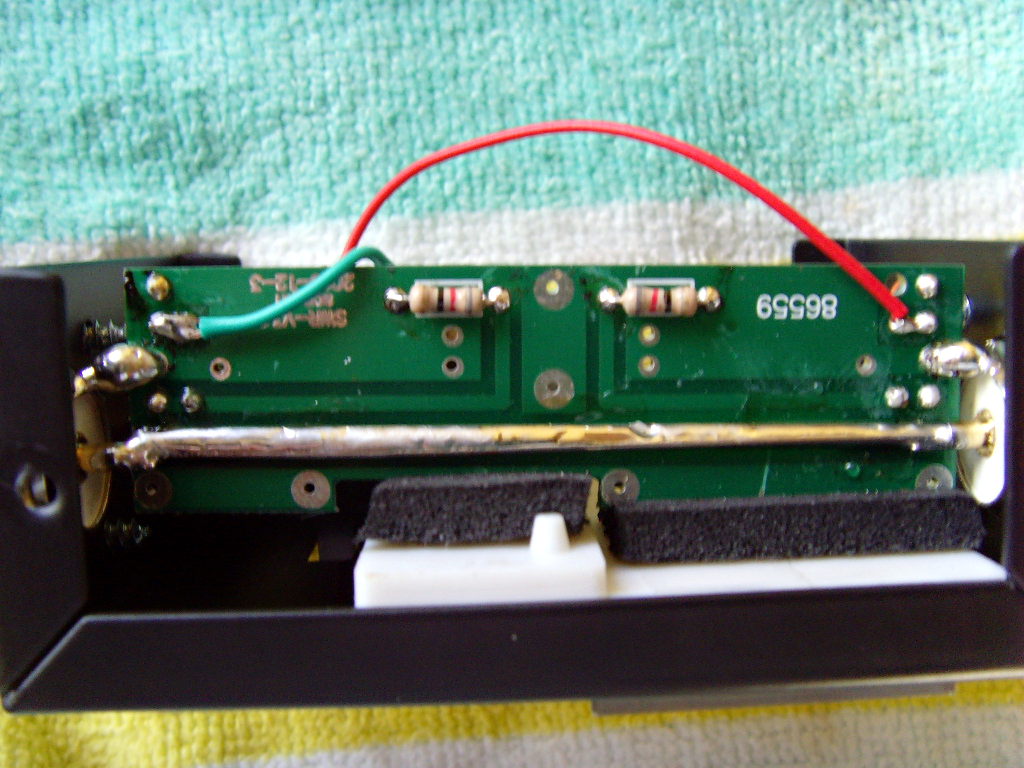
OK, (2) 82 Ohm resistors....no other components inside the unit other than the slide switch and the main adjusting POT.
Looks like a pretty standard design. The 10 pF capacitors are apparently placed at the sense line end to roughly equalize the frequency characteristic. You can expect about ~f sensitive at lower frequencies, e.g. 65% of 120 MHz response at 80 MHz. Just consider, that the coupler is already operated far below wavelength dimensions at specified frequencies, there's no strict cut-off frequency. The implemented measurement rectifier is even DC-capable.
Does all that technical talk translate into leave it as is for the 80 -120mhz range?
Thanks
Wow, that really is a dual directional coupler measuring forward and reverse travelling waves! Unfortunately, if you just add bigger capacitors (than the 10 pf) to lower the bandwidth the directional couplers will lose their "directionality". How many watts are you transmitting? If it is small, you could add a lumped element directional coupler from minicircuits in there.
The real solution for high power is to build a much longer dual directional coupler (using FR4 board, 2 concentric copper pipes, or something like that).
Only plan on 10W or less.
I would try with the device as is.
I'm trying it right now. I have a 1W Fm transmitter set at 93mhz and connected to the swr meter with a very short piece of coax. I have a dummy load connected to the swr meters ANT output. When I go to set the meter(Place switch in the "Set" position, then power up the transmitter, and adjust the knob until the needle is lined up with the infinity sign on the right side of the scale, then you click the switch to SWR to get the swr reading)....When I do this, the needle will not move to the right for me to "set" the meter before I switch to SWR to get the reading. It moves only 1/4" to the right during the set process.
Thanks
You are in luck. Minicircuits makes a SYDC-20-13HP+ dual directional coupler (20 dB) for S29. You would put this in place of that printed dirctional coupler, and add a Tee pad for another ~15 db of attenuation before the diodes. Then you would have a really accurated 40 to 1000 MHz swr meter.
I just added 8pF to the input side of the meter where the 10pF is mounted. I am now able to set the meter. Should I add the same amount to the other 10pF cap? I left everything else untouched.
Thanks