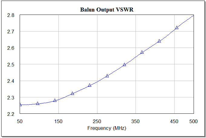
High balun output VSWR
I simulated and measured a series of baluns (e.g. TC1.5-52 from Minicircuits) and had the VSWR responce as shown at the picture attached.
It is a 1.5:1 balun, the input impedance was 50 Ohm, each of the outputs from the balanced side was loaded to a 37.5 Ohm impedance to have a 75 Ohm differential impedance. Input VSWR was about 1.5:1, which is acceptable.
What's your setup for measuring output VSWR? Did you make sure to set the Z0 of your source on the secondary to 75? Otherwise you'll see VSWR rise by a factor of ~1.5.
I use resistive impedance matching network and then recalculate the resulting impedance to get the "real value" on few frequency points. Not sure this is a correct way - nevertheless the results looks similar to the simulated ones. In my case it is more important, why simulation, where everything seems to be correct (see my first message), shows bad VSWR from the outputs. Nevertheless the results looks similar to the simulated ones.
Here it is more important and interesting why already in simulation, where everything seems to be correct (see my first message, I used s-param file for TC1.5-52 balun), VSWR from the outputs is bad.
According to the data sheet return loss, VSWR would range from 1.08@50 MHz to about 2@500MHz.
Looks like some principle mismatch is involved in your test setup.
I couldn't find the datasheet of the balun but the specifications may have been given according to 50 Ohm.When it's used with 75 Ohm port impedance, the specs. can differentiate..
It is not quiet clear from datasheet, but seems that VSWR is given for unbalanced 50 Ohm input.
I am talking about the VSWR from its balanced outputs. Ports 2 and 3 on the picture attached. Ports was placed according to pin configuration described in s-param file.

You can not understand drive mode at all.
You have to drive port2 and port3 with 180degree-phase difference.
[Note]Three ports S-parameters are in condition of single-ended drive at each port.
There only one port can be active at same time.
This is true for both actual measurement and EDA-Tool-Play.
You can calculate gamma for any drive condition from {s11,s12,s13, s21,s22,s23, s31,s32,s33}
as far as DUT is linear.
See https://www.edaboard.com/showthread.php?t=365152
However it is easier to drive port2 and port3 with 180degree-phase difference, since your concerns are no more than EDA-Tool-Play.
There you have to use AC-Analysis not SP-Analysis.
You can expect similar VSWR as for the input if you drive the output with a balanced 75 ohms port. Determining VSWR for a "half" balanced port makes no sense.
Thank you! Now everything became clear.
Thanks! Now I understand.
See case of Rdummy=0 in https://www.edaboard.com/showthread.php?t=352410#2
Another technique is to cascade two baluns.
SE-->BAL-->BAL-->SE.
This also gives an insight.
Yes, I used to do like this. Yet I suppose that this way gives rather rough and not reliable results, doesn't it?
I mean this is not suitable for a verification of a device, where balun is used.
This can be useful only for insertion loss evaluation.
You can not evaluate output impedance.
See the followings.
http://www.designers-guide.org/Forum...1233236788/1#1
http://www.designers-guide.org/Forum...1240201234/1#1
Thanks!
For insertion loss measurments now I use a resisitive matching network. This method was described in a paper "HOW RF TRANSFORMERS WORK AND HOW THEY ARE MEASURED" by Mini-Circuits engineers. This way shows a good agreement with simulation and with expectations.
NOT all baluns are matched at all three ports! what type do you have?
A lot have good output power matching...but do not mention the high vswr they have!