Tuning a series LC circuit, different ways?
1. L stationary, C mechanically tuned (variable capacitor)
2. L mechanically tuned (inserting or removing cores), C stationary
3. L stationary, C varicap
4. L electrically tuned (varying magnetization of the core by a closely placed electromagnet), C stationary
5. Combinations of all the above
Any other methods that you can think of?
you can have switches to change the length of inductors. same thing for capacitors.
If you vary L you will affect the bandwidth of the tank as well. That is why it is preferred to vary C to tune a LC tank.
Do you refer to the Q of the tuned circuit?
2a = ferrite core = +20%, 2b, copper core = - 20%, 2c L , two coupled Ls, change angle between Ls change = L1a + L1b +- Lm (see goniometer).
Frank
A problem of method 1. is the microphonism of variable capacitors when subject to movement or vibrations.
For this reason, method 2. was used in old car radios.
Method 3 is used in modern radios.
Another method is using a variometer, i.e. a series combination of 2 coupled inductors with mechanically variable mutual inductance, like this:
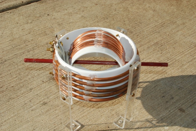
Ltot = L1 + L2 + 2*M where M=k*sqrt(L1*L2) and k can range between -1 and 1 .
Regards
Z
Yes, a variometer, well known from the crystal radio era.
I like the varicap method but If you listen to a varicap oscillator signal on an SSB radio it shows tone fluctuations, possibly from fluctuations in rf voltage. I have tried varicaps in 2-3 different circuits and they all have these fluctuations. The "real" LC circuit is much more tone clear :(
I was hoping to find a way to avoid these harder to find and expensive variable capacitors with reduction drives
Yet another possibility is the reactance modulator: a transistor (or a tube in the old times) presenting a reactance (inductive or capacitive, according to topology) whose value is varied with the transconductance of the device. Transconductance is controlled by the operating point of the trsansistor.
When C is varied in an LC circuit, the resonant frequency changes but the bandwidth remains constant.
This is important because it is imperative that the bandwidth of an LC circuit remains the same throughout
the tuning range. If L rather than C is varied, however, the bandwidth would vary throughout the tuning
range of L. Specifically, if the circuit's resonant frequency is doubled by reducing the value of L, the Q of
the circuit is halved and the bandwidth is quadrupled.
Conversely, if the circuit's resonant frequency is halved by increasing the value of L, Q doubles and the
bandwidth is reduced by a factor of 4. The condition of a varying bandwidth is highly undesirable. This
is why an LC circuit is usually tuned by varying C rather than L.
It's not correct..For series resonant LC circuit
Q=(1/Rs)xSQRT(L/C) and BW=Fo/Q
So, when you change C or L, the bandwidth will also be changed.
I would like to see an example of this technique
- - - Updated - - -
Maybe that is why there are so different L/C ratios that can be used for a frequency range, but only some are usually chosen. For example one does not use a very small cap in combination with a very low inductance and vice versa
The reason that the bandwidth does not change when C is varied is that the Q of the circuit
varies in direct proportion to the resonant frequency. That is, if the resonant frequency is doubled by
reducing the value of C, the circuit Q also doubles. Conversely, if the circuit's resonant frequency is halved
by increasing C, the circuit Q is also halved. Since BW = fo/Q, it is obvious that there can be no change
in the circuit's bandwidth as C is varied throughout its tuning range.
In the following, let's consider series and parallel circuits having 3 elements (L, R and C) and narrow-band aproximation (i.e. Q>>1).
G=1/R is conductance.
For a series circuit, the impedance is
sL + R + 1/(sC)
The 3-dB bandwidth is Δω=R/L, i.e., it does not change with C.
We have the dual situation as follows:
For a parallel circuit, the admittance is
sC + G + 1/(sL)
The 3-dB bandwidth is Δω=G/C =1/(RC), i.e., it does not change with L.
Regards
Z
- Questions about S22 calculation of frequency tripler in ads simulation
- MC145151/2 p2 calculation dip swich vs xtal divader
- How to calculate bandwidth for this circuit, including lower and higher cut off freq
- Re: Calculate Capacitance Value from Smith Chart
- Calculate Capacitance Value from Smith Chart
- Calculating total radiated power (TRP)