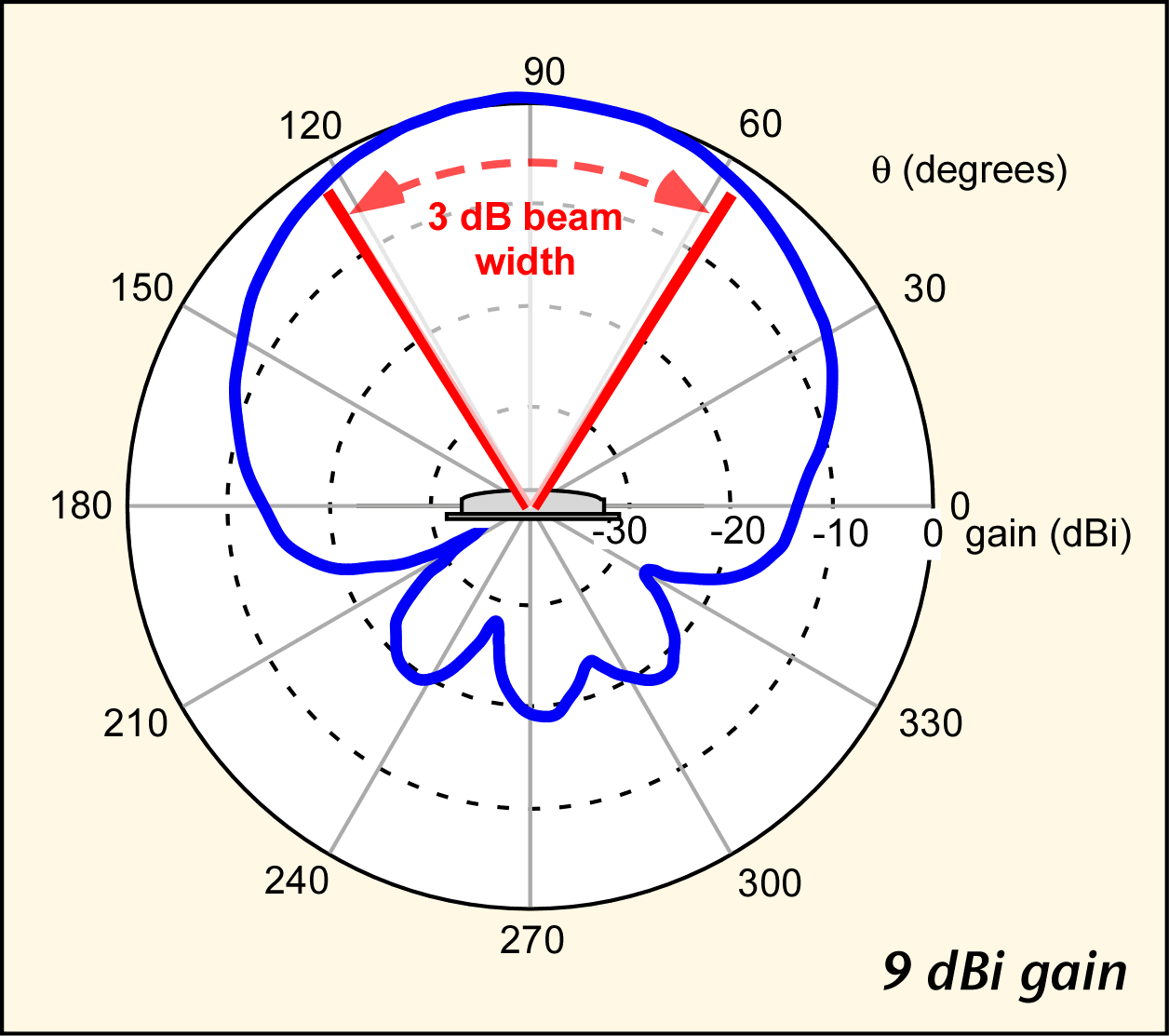
Patch antenna ground plane effect on radiation pattern
I understand that a patch antenna has a radiation pattern similar to the following picture (from Wikipedia) when the patch antenna is centered over the ground plane.


It"s not feasible to center the antenna in the devices I worked on, so we'd kind of shove the antenna in the corner of the PCB.

At my previous company, the RF engineers told me that the antenna pattern would be pulled in the direction of the closest ground plane edge. Thus, if I put my antenna at the "top" of my PCB, the pattern would be pulled "up". Since they were the RF engineers and I'm not, I took their word for it.
At my current company, the RF engineer (singular) tells me that the antenna pattern will be pulled in the opposite direction, that is, toward the larger ground plane area. So if I put my antenna at the "top" of the PCB, the pattern is pulled "down". His explanation basically amounts to "I'm an RF engineer and you're not, so take my word for it."
I'm looking for some actual documentary evidence that will corroborate one version or the other, so that I'm not relying on hearsay. I've found plenty of stuff online that describes the relationship between ground plane size vs. gain, but nothing about ground plane asymmetry and its effects on directivity. Does anybody know of any articles that might describe this?
It would be best to simulate each case. "Rules of Thumb" don't always work. Without citing an article (Just Google it.), I would probably usually tend to agree with the RF engineer at your current company, for some types of antennas.
I'm not an RF guy, so I don't have any simulation tools, nor do I know how to use them. Do you have some suggestions for simulators I might try (for free)?
I did Google it, and everything I found related to ground plane size vs. antenna gain. Nothing appeared to reference shaping the directivity.
The 4NEC2 software is very good, and is free.
"At my current company, the RF engineer (singular) tells me that the antenna pattern will be pulled in the opposite direction"
This "singular" RF engineer is the smart guy. Ignore the RF engineers from the previous company.
