Ripple Effect on RF Amp Design
Please refer to it
It seems to me this effect could be due to a long (referred to lambda) poorly matched transmission line. Is your network analyzer calibrated at the end of the connecting cables ? Can't you measure S11 and/or S22 ?
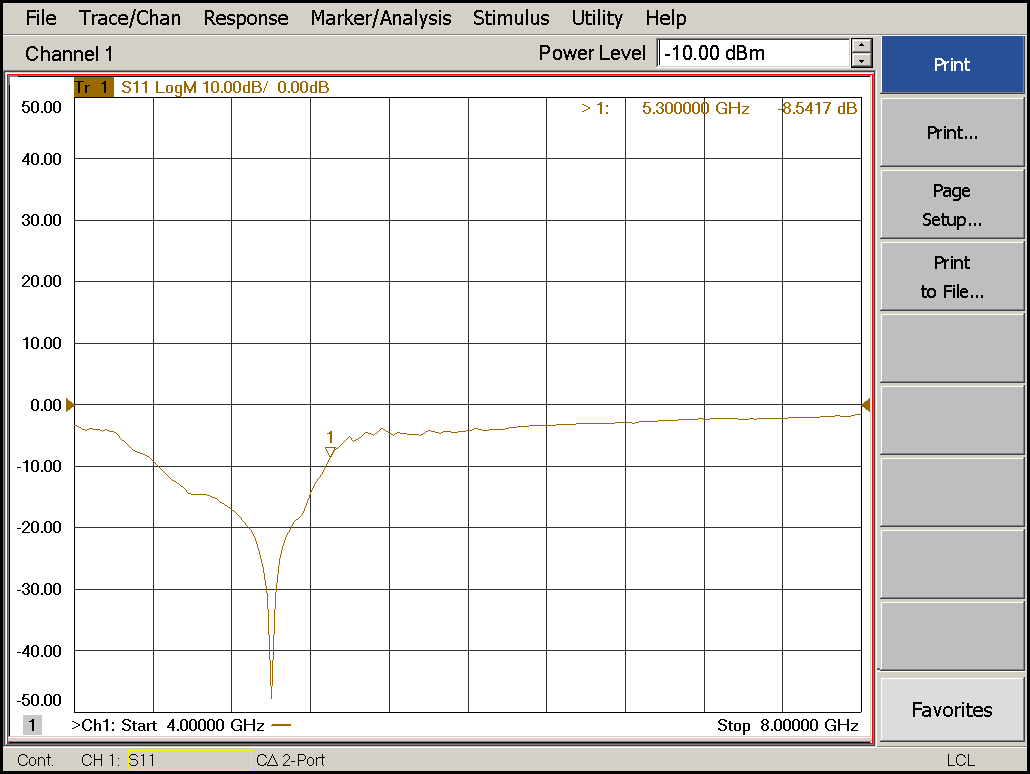
Hi, yes, i have measured S11 too. as per attached is the result of measured value for S11.

May be caused by poor match of your RF amplifier on the input or output, i.e. VSWR.
You can insert a PI attenuator at the input to see what happens.
It is oscillating at out of band.
Yeah looks like some weak oscillation or other interfering signal. Try reducing your IF bandwidth and see if it changes.
Hi, is there any term for this problem? Is there any suggestion for the reading?
- Effect of number of fingers and width of a transistor on Efficiency and power gain
- What is the effect of power match on S11 and S22 in a PA
- need ways to access the isolation effects of GND vias in PCB layout
- Bonding material effect on stack patch antenna
- Effective refractive index of a slab waveguide
- Effect of flip-chip bump inductance on the amplifier.
