how to extract RF Tx from CDT401 remote
Please give some details on your transmitter. You can possibly tell from looking on the transmitter module where is output is connected to the antenna,where the DC power is input, and possibly the pin to which the remote-control digital code enters.
Best is to have a schematic.
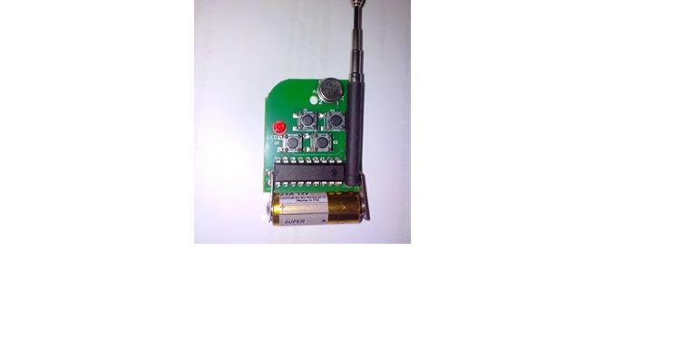
i am attaching schematic and screen shot of original module , that may be helpful for you.
actually schematic attached is of encoder ic that is used within this RF Transmitter module, so if that may help to find transmitting portion. plz reply soon
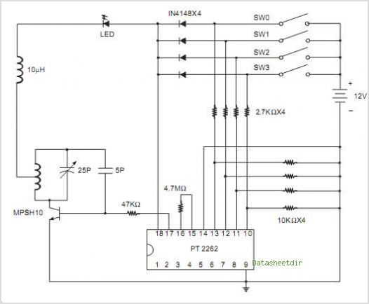
Couple a small wire loop, ~1 cm in diameter , to the oscillator coil. Connect the col to a coax cable, and tune the trimmer to a desired frequency.
The real circuit. however, shows to coil but a SAW resonator. Then use a 1...3 pF capacitor and connect it to the antenna point to get the RF signal out.
i am actually trying to do transmission over RF using manchester coding , so all i am concerned about is where to give input to this transmitter so it may transmit to receiver side
The modulation input can be made to RF transistor base through a 10 kOhm resistor. I would disconnect the 5 kOhm resistor from the IC and while the 10 kOhm resistor is connected to transistor base, the other resistor end should be blocked to ground line by a 100 pF...1000 pF capacitor. This will not affect the modulating signal and will block the RF to travel along the modulation line.
but my problem is , i want extract my Rf transmitter from above shown remote circuit with encoder ic patched over it, and then i want to synchronize this with microcontroller so how am i suppose to look for the base transistor in that?
As you were able to show the schematic and a photo, you should be able to find the RF transistor and identify the base with the 5k resistor. Then follow what I wrote.
If you cannot, find a radio amateur who could do it. I do not know how I can help you from here.
ok thats pretty helpfull.i got your point. thank you very much
ok so i have located the transistor base with 5.6k resistor? can you tell me why have you said about replacing this resistor with 10k value?
The 10k value will protect the transistor from the excess current coming from an external modulation source. A typical RF transistor with beta >50 needs less than 0.1 mA current to open.