Impedance matching problem between LNA and Mixer
you do not tell us how long the interconnecting transmission line is, nor how much amplitude ripple you can live with over a bandwidth.
If they are really close, just hook one to the other. If they are far apart, you could add a series resistor at the mixer, and run 75 ohm line.
if it is narrowband, you could just run 50 ohm line from the lna, and then do a L-C matching network at the mixer. alternatively, if you have the room on the board, you could do a quarterwave transmission line transformer with a characteristic impedance Zt=√(50 * 75)
Hi biff44,
Thank you for your reply. The interconnecting transmission line is about 1.5cm. The working frequency is from 1.2 GHz to 1.6 GHz and the wavelength is about 12 cm. In fact my whole design process is this:
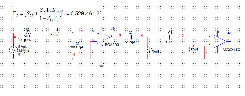
1) I choose a optimum source reflection coefficient Γs=0.3165∠83° on Smith Chart for LNA based on the equal gain circle and equal noise figure to get the ideal gain and noise figure.
2) I then did the input matching to 50 Ohm for the chosen Γs using LC network as you can see in the attached image.
3) I calculated the corresponding ΓL = 0.529∠61.3° using formula in the attached image in order to do conjugate matching.
4) Match the calculated ΓL to 50 Ohm using one LC network1 (C3, L2), then using another LC network2 (C4,L3) match 50 Ohm to 75 Ohm of the input impedance of MAX2112.
So my question again:
1) do you think matching the calculated ΓL to 50 Ohm not necessary or matching 50 Ohm to 75 Ohm not necessary? Will it have best gain and noise figure if I do both?
2) do I need to add DC isolation capacitors in serial for both input and output of LNA? What if I add a 470 pF DC isolation capacitor or another LC network with large values( say 470pF capacitor in serial and 56nH inductor in parallel) for both input and output? Do you think it is a good idea and necessary?
Thanks and regards.
BGA2001 according to its data sheet is matched to 50 Ohms and requires DC blocks at in and out.
The 75 Ohm mixer calls for 75 Ohms for a wideband operation but as above stated, a short connection 5o or 75 Ohm line between both can work without problems.
Please make sure your LO input power to the mixer can be adjusted some +/- 3 dB around the specified value. This level affects mixer input impedance.
As BGA2001 has almost 20 dB gain, you can afford to install a 100-Ohm SMD trimmer in the connecting line between LNA and mixer, and adjust an optimum flatness over the RF band.
If you use a RF bandpass filter before LNA or before the mixer, I would recommend a tunable version to optimize conversion gain flatness. Then no connection line problem will exist, only a careful filter tuning is needed. Also the IF filter after the mixer may need some adjustment for the best results.
Be ready to experiment, good luck!