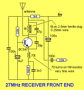
few questions regarding 27MHz receiver
I am checking the circuitry for a 27MHz regenerative receiver.


These are all the circuits which I am referring from internet. Also I found similar circuitry from the chinese toy car receiver circuit which uses the RX2B TX2B decoder encoder IC pair along with these kind of super regenerative receiver.
The working seems little bit weird, ie the receiver itself try to transmit a very weak 27MHz frequency and if any external strong 27MHz is there around the receiver antenna, it makes it difficult for the receiver antenna to transmit the weak 27MHz signal and thus disturbs the receiver and makes it take less or more current than usual and by detecting this change in current we demodulates the signal.
Now my questions are,
1>
How can we increase the receiver sensitivity of this kind super regenerative receiver?
It is using only single transistor for RF receiving and after that all the stages are only low frequency amplification, means we are getting the demodulated signal from the TOP of inductor, yes right I agree it is a nice way to demodulate. I tried to amplify the RF part by coupling the RF signal (collector of rf transistor) to a second stage of 27MHz tuned amplifier. But this behaves a bit weird and seems not very effective because it is a regenerative receiver and the weak receiver signal itself is getting amplified and thus making it very difficult to tune it to make it not oscillate due to the weak signal of receiver.
2>
What is another better method for this apart from a super regenerative receiver technique ? Is this improves the receiver sensitivity?
Super-regen receivers are the simplest and offer a good sensitivity. They have problems, too:
- they receive a wide bandwidth which means they are prone to interference.
- some require adjustment to get the best sensitivity, and connecting an antenna changes the adjustment.
Modern receivers use superhet concept as low-cost ICs are available. Using filters reduces interference and no adjustment is needed.
A regenerative receiver uses positive feedback just short of the point of oscillation to in increase the Q of the tuned circuit, and hence the voltage multiplication.
A super-regen allows the transistor to go beyond the above point and actually oscillate, but this causes the transistor to switch of by a change in DC bias. After the circuit has discharged the process is repeated. This means that the signal being received is being chopped at a super sonic frequency, so you do not hear it. The relatively large RF choke in the emitter circuit is part of the super sonic oscillatory system.
A super regen is more stable the a simple regen as the transistor is reset every 20 micro seconds or so, and its whole characteristic is being used, while the simple regen is balancing just not on the point of oscillating.
Frank
3 pin ceramic resonators are common in low cost Rx radios for the IF filter at 10.7MHz and LO = 28MHz+10.7MHz for low leakage of LO and low insertion loss of BPF.
http://www.digikey.com/product-searc...ilters/3409155
This allows lower noise floor and lower injection required to stimulate mixing and improved image rejection and adjacent channel interference.
I never made an extremely cheap regen or super-regen radio but I believe they are overloaded by all the strong local radio stations around my city.
