Isolation between LC-VCO and loop filter
When the loop is running the oscillation frequency of the VCO is getting coupled though the moscap to the loop filter. Even after the loop is locked I am getting oscillations at the loop filter output. Needless to say that spurs are generated due to this...
How can I isolate the loop filter from the moscap?
Is there a large resistance between MOS cap and Loop-Filter output ? There also should be a capacitor at the end of the Loop-Filter. If you see the VCO oscillations at that point, it means the last cap. has been selected high ESR or inconvenient model.
It's not obvious why VCO leakage back to the filter causes spurs (in other words an unstable PLL). More likely this happens due to unsuitable PLL parameters.
There could be however a problem if the leaked RF is overloading the buffer amplifier.
FvM:
I simulated the PLL with same components except using an ideal oscillator from the library. The loop filter output after lock was perfectly constant. PFD input edges were matching perfectly. There were no spurs at the VCO output.
BigBoss.
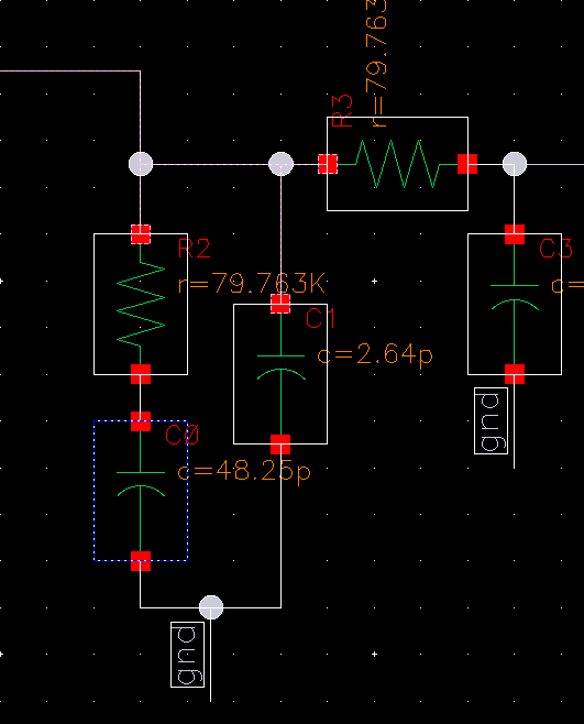
This is the loop filter I'm using

I am using ideal resistors and capacitors. Yes there is large oscillations at the loop filter output. Should I increase the final capacitance value?
Your component values seem incorrect, pF level caps. are not usual PLL loop filter elements. Calculate them again with a proper calculator and try to do simulation.
My charge pump current is 2uA. So the capacitors are not large...
- Questions about S22 calculation of frequency tripler in ads simulation
- MC145151/2 p2 calculation dip swich vs xtal divader
- How to calculate bandwidth for this circuit, including lower and higher cut off freq
- Re: Calculate Capacitance Value from Smith Chart
- Calculate Capacitance Value from Smith Chart
- Calculating total radiated power (TRP)
