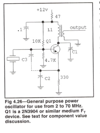
impedance matching oscillator and amplifier circuit
I have a L1 reactance of 450 ohm with 36 turns and I'm trying to drive that to the input of my amplifier circuit with a 50ohm input reactance.
1.to do this would I need 12 turns on the secondary to make 450 look like 50 ohms on the input of the amplifier.
2.once these two are connected and working, I'm suppose to do the impedance matching from the amplifier into a 50ohm dummy load to test, if there is indeed 10watts of power and the 13.56mhz wave. The output of the amplifier consists of low pass filter for harmonic attenuation but this can be ignored. I don't care about harmonics in this project, so from the L-C-C network to a 50 ohm dummy load, can I just connect the dummy load on the out side or do I have to do some kind of LCC network again to match the output impedance of LCC to the 50ohmn dummy load.


If point B is 50 ohms (as should be) you can connect directly to that point a 50 ohms dummy load, and keep the PI network for impedance matching between PA transistor and the load.
as far as hooking up the circuits is that correct. in order to drive the output of the oscillator to the amplifier, I have to 450 look like 50ohm on the input of amplifier so that would require 12 turns on the secondary. 450 reactance requires 36 turn on primary.
The turns ratio depends on the output impedance of the transistor. The Vb is 4.7/14.7 X 12 ~ 4V so Ve ~ 3.3 so the Ic is 10mA. This is the standing bias on the transistor. During the oscillation cycle it is impossible for the current to go down to zero , so the negative peak RF current is say 9mA. I would presume that the positive half cycle would be much the same (at a guess). This means that the p-p RF current will be 18mA or about 6mA RMS. So with a total voltage excursion of a bit less then 24Vpp ( 2 X Vcc for a transformer load), the output impedance should be 8/6 K or 1.2K ohms, so a higher turns ratio might be required. It depends on how lively the oscillator is, could be the RMS current could be only 1mA.
I don't like C1, if the secondary is tightly coupled and has a resistive load, T1 should be resistive and the capacitor will only reduce the output.
Frank
I'm sorry I left out some stuff out that might clear things up, from the book it says the oscillator has a L1 that uses a toroid with reactance of 250ohm and I'm using the t37-2 toroid. With that said and putting this into a "toroid calculator" or using the "inductor reactance" or "resonate frequency" formulas, we get 27 turns, C1 with 47pf, and L1 of 2.93uf. and it says from the book that the output link uses 10 to 20% the turns on L1. I would assume using the "turns ratio equation" Np/Ns=sqrt(zp/zs) giving a output link of 3-9ohms. And if I want to make 250 look like 50ohmn for the input amplifier connection just use the "turns ratio" again. Now is that correct?
Note: I made more turns on l1 to get it to 450ohmn reactance to give a higher power output for the amplifier, then used the "turns ratio" to match to 50ohmn. primary turns then were 36 turns,c1 went to 26pf, and L1 5uH.
2.93uH not 2.93uf
Because the oscillator is unbuffered, any change in the collector load will reflect in a change of the oscillator's activity. If you are doing this at home, I would just use a voltage peak detector across a 47 ohm load and measure the output on a meter. This way you can adjust and get a true max. If you have a PA transistor, then measure its collector current it will rise as more drive is applied. Because as sure as, eggs are eggs, the input impedance of the PA will not be 50 ohms.
Frank
