RE: RF Filter prototyping
Thank you
Use the type of design in your prototype that you intend to use in the final design.
Depends on your filter. Probably any filter over 3rd order should be on surface mount. I've been on SMT for over 20 years and I find it much easier to design a working filter, since stray C's and L's can be made much lower.
Thanks SLK001, but how do you make your prototypes?
Is there a prototyping board that you recommend?
How do you go about choosing your components to make sure they behave as expected at these frequencies?
In general you'll select L:C ratio based on available current going through the filter.
Low A, low C, high L.
High A, High C, low L.
Output (load) resistance is a chief factor as well. All these factors determine the shape of your rolloff curve.
Consider various combinations: LC series, LC tank, twin tee, etc.
Simulation showing how L:C ratio affects bandwidth.

A Band reject filter should have certain specifications such as; In-Band Rejection/Attenuation,3dB ( or 1dB) Corner Frequencies,Out-of-Band Attenuation and Ripple,Group Delay if it's requested etc.
No one can suggest anything without knowing these specs.
There are many good tools to design this filter such as Nuhertz Filter Design Tool or Ansys Nexxim Filter Wizard etc. There are also well online design tools on the internet.
SMD components are pretty convenient for this band and there are many manufacturers such as Murata, Kyocera AVX, Toko etc.But thru hole components can also be used with paying some attention on board implementation but I do not personally recommend thri hole components for a novice.
I always had a prototype PCB made with the EXACT layout that I intended to use. Costs money, but saves time and money in the long run. I start with a design using the topology that I selected. Once satisfied with the results, I select an inductor set that I have (or can get) that is as close to the designed values as I can. I then use these new values to optimize the design using ADS. If the design optimizes to my satisfaction, I will lay out a prototype PCB using my values and once I receive my PCB, I will then build and optimize once again.
try these boards:
http://www.ebay.com/itm/171656037544...%3AMEBIDX%3AIT
Is it possible to tweak these to the exact frequency that I need?
or did you mean something like the RF Biscuit?
The filter in the post #7 link is a low-pass, you need to change the topology to make it a band-pass.
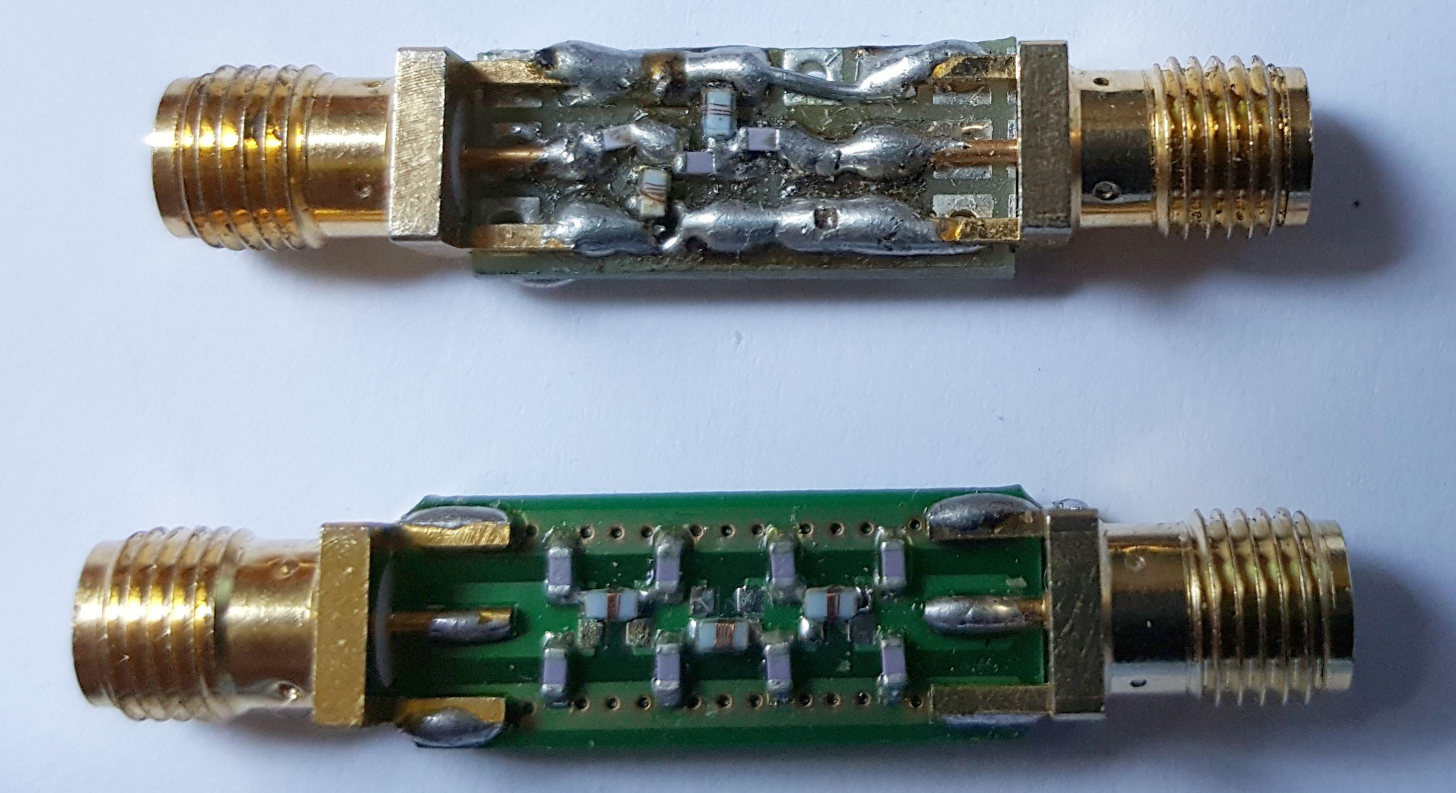
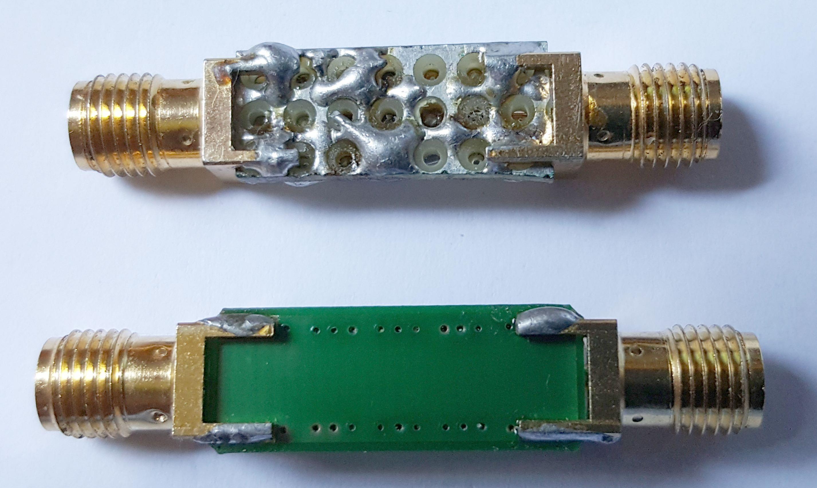
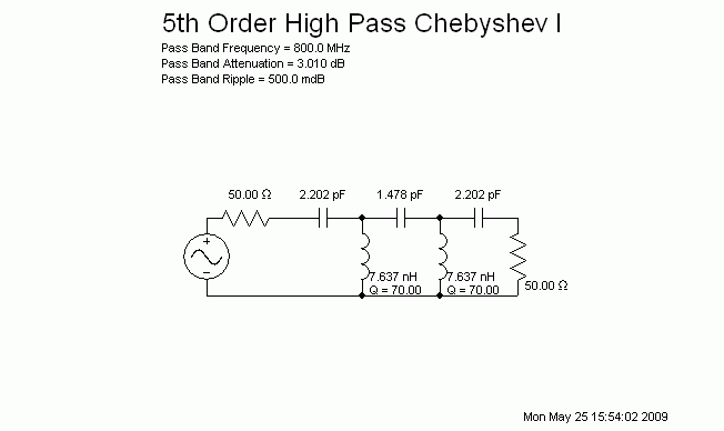
I have previously implemented SMD filters on a RF prototype board, see the 800 MHz high-pass shown below. The actual filter characteristic matches the theoretical curve nicely. Clearly it's much easier to use a PCB as for the low-pass filter shown on the photo.
Both filters use 0603 wire-wound inductors and NP0 capacitors. 0603 offers a good compromise between RF behavior and component handling for the sub-GHZ range.


