Connectong two or more varicaps in series to reduce minimum capacitance?
The total maximum capacitance will be reduced too but this is not so important to me.
You just connect them in series with the positive supply ends joined, and going to your tuning voltage through a high value resistor.
I think that needs qualifying by adding there must be a DC return from both anode ends to the negative side of the tuning voltage!
In other words, join them cathode to cathode, feed the tuning voltage to the junction and make sure there is a DC path, even if high resistance, from both anode ends back to the tuning voltage negative side.
Brian.
Yup, ^^^ what he said.
It was assumed these varicaps would be wired directly across the relevant inductor which would supply the necessary dc path..
If a differential mode is not considered, I'd prefer to use single varicap but lower cap. values.Because series connected varicaps wil have higher loss parasitics such as package bonding inductance, series resistances etc. so each parasitic will reduce the overall quality factor of the tank circuit.
Indeed my varicap is not connected to a coil but to a crystal and the top end is DC isolated.
This is what I was thinking (attached).
Varicaps are 30-500pf types (1sv149, bb112 etc). Resistors are 100K. I am not sure if they have to be 1M better.
Capacitors are 100nF
With this configuration, the total capacitance should vary from about 10pf to 160pf or so.
160pf is still plenty (HF use) since the mv209 I now use has only 50pf max or so. I could use BB212 back to back but they are rare and expensive!
What do you think of my circuit?
It will work at HF but at higher frequencies the parasitics BigBoss mentioned will swamp the capacitance anyway. A reverse biased diode does not draw significant current so whether you use 100K or 1M will make little difference to operation but the capacitance of the resistors themselves will make a small difference.
Just a thought - if you have a capacitance meter, try using normal silicon diodes instead of varicaps. Their capacitance characteristics are poorly matched for this application but by testing you can probably find one with enough capacitance swing. Like fixed capacitors, the value depends upon the area of the plates and distance between them, in a diode that equates to the area of the junction and width of the depletion region. You may even find that diodes like the 1N400x series work quite well because they have large junctions.
If you have a tester, wire it as in a tuned circuit (but without the inductor!) and add a fixed series capacitor of say 10nF. Feed it with an isolated voltage from a battery so there is no risk of injecting DC into the meter or measuring the battery itself.
I just tried doing that here and got some strange results - diodes measuring several uF! The cheap LCR/semiconductor meter I used calculates values using time contants of the capacitor charging between two MCU pins and it has an automatic component identifier. It was charging the series capacitor through the diode and getting very confused when it couldn't discharge back again! If you have a meter like mine (which is fine for single components but not several connected together) I would suggest using a real LC circuit and measuring the resonant frequency instead.
Brian.
And, do I read you correctly, you are trying to tune a crystal using a varicap?
Modern crystals are high-Q devices and a varicap on the legs will have little effect, if any.
Not a crystal a ceramic resonator. Currently it is tuned to +/- 50KHz.
I tried the 1M with the single varicap and I had a strange microphonic. So I decided to use 100K with the multiple varicaps circuit I posted. My concern is if there would be some strange parallel capacitance interaction due to the VCC resistors connected in parallel.
Also if this circuit can be simplified more (less capacitors/resistors?) I would love to find it how.
Perhaps you can get +/- 10 or 20 KHz range; if you try harder, the resonator will go out of lock and will take time to come back to lock - perhaps you can see (or hear) something like motorboating.
You will need some thing to broaden the Q- flatten the curve- perhaps it is worthwhile to try to increase some resistance somewhere...
No, it does tune, more specifically from 7.003-1.105MHz with a 7.160MHz resonator. It is only the low end of the varicap that limits the higher tuning end.
I did something like this myself, tuning a 500 Khz two terminal ceramic resonator for use as a BFO. I spent several days messing about with different varicaps and different oscillator circuits, trying to get a wide enough tuning range using a tuning voltage maximum of only 12 volts.
The problem was mostly at the high frequency end, and I had to select one out of the ten ceramic resonators that I bought to find the one with the highest natural frequency.
Anyhow, what I ended up with tuned from 497Khz at 0v, and 503 Khz at +10v. That does not sound like much, but remember its only 500 Khz.
At 7Mhz you may be able to get fourteen times the range, maybe 84Khz wide ?
I don't know if this circuit will be of any help to you at 7Mhz, but its what I ended up using. The tuning is amazingly linear, within a few Hz of the exact frequencies.

I have to correct something. With the varicap IN PLACE my circuit tuned about 80KHz indeed. With the varicap disconnected the resonator tuned to 7.105 (natural frequency). It is the minimum capacitance of the varicap that causes this 80KHz limit, that's why I thought to correct this by connecting varicaps in series.
I do not think your circuit will be useful in my circuit topology, I do not see how it can apply to it, but many thanks!
I agree, my circuit is not really relevant, but I too had problems reaching the high frequency end. Only solved by hand selecting a resonator with the highest natural frequency.
I had much more success with that, than using lower capacitance varicaps which lost me more low end than I gained at the high end. You could try using a much higher tuning voltage, but even that has its limits.
Yes I found these limitations myself as well. Since I need to replace the mv209 (8-50pf) with something that has more range, the only solution (without using switching) seems to be connecting more higher capacitance varicaps in series, so that you end up with quite a high capacitance ~160pf and also quite low, like the mv209 or better.
It is also cheaper to use something like 1sv149 instead of the obsolete and expensive bb212
The starting point is probably to use a varicap with the largest ratio of capacity change.
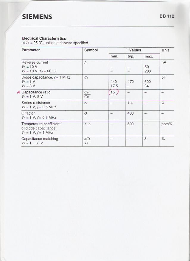
The BB112 I used, has a specified capacitance range of 15:1 with a tuning voltage of 1v to 8v. It was the best thing I could find in that respect.
Using two in series just halves the capacitance at both ends of the range, it will not get you a greater tuning ratio.
Yes but even at 3 in series, the capacitance is still quite large at 160pf or so
I could not find a higher capacitance radio varicap, have you?
I would not be too concerned about the actual capacitance values.
If this was an LC circuit it would tune over at least a 3:1 frequency range, possibly reaching a 4:1 frequency range.
But these ceramic resonators are a mechanically vibrating lump of "stuff" the capacitance change has minimal effect, so we need a very large capacitance change to get a very small frequency shift.
In my case 6Khz/500Khz = only 1.2% change in frequency.
Try putting some fixed capacitors across your resonator, see what happens. That might give you more of an idea about what you need to do the job.
I never actually tried that myself, maybe I should have.
It may possibly have saved me a lot of very frustrating trial and error experimentation.
It is the higher frequency that achieves the greater pulling. At 7MHz it is quite a lot, covering a bit less than half of the band, whereas at 500KHz it is very low.
A note, they say at higher frequencies (above 10MHz or so) thermal issues affect the frequency stability, but I bet it would be better than LC. The only problem I find with ceramic resonators is the lack of availability for some ham bands.
It is strange that you can tune a ceramic resonator of 7.160 MHz from 7.003-1.105MHz; such a large range is usually not possible; the oscillations are no more locked to the crystal and there may be other problems.
varicaps Connectong capacitance 相关文章:
- How to take ESD and pad capacitances into consideration during design
- Re: Calculate Capacitance Value from Smith Chart
- Calculate Capacitance Value from Smith Chart
- How the capacitance varies as input power varies in a mmW RFIC PA?
- How does the capacitance of a patch antenna affect its resonance frequency
- Calculate capacitance on SRR