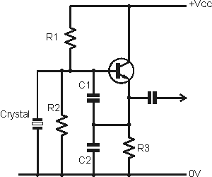
Selective Crystal Oscillator
http://www.radio-electronics.com/inf...oscillator.php
I am confused and can't understand how the tank circuit, which is open at resonance, and the transistor pass the 2nd or any other harmonic of a crystal of a fundamental frequency of, say, 48 MHz.
What frequency is at the output if the tank is open at resonance 48MHz for example?
1. How does the tank circuit contribute to or govern the choice of the desired Harmonic at the output if a parallel LC is "open circuit" at resonance?
2. How can I calculate L1 and C4 to have the desired frequency at the output?
Do I have to include the transistors' output capacitance in calculating the tank circuit? What is formula for that?
Many thanks in advance!
There's no L1 or C4 in the linked schematic...
You are linking a common collector colpitts oscillator and saying it's equal to different circuit by adding a collector tank. That (if true at all) is surely not a usual oscillator prototype.

Please show a schematic that fits your question.
The term "selective crystal oscillator" would be primarily associated with a circuit forcing a crystal oscillation on a specific mode or harmonic respectively suppressing other modes. Second harmonic is no useable crystal harmonic. To make a CC colpitts "selective", the LC circuit would be added somehow to the emitter-base feedback path. e.g. in parallel t the crystal.
Harmonic frequency multiplication of a fundamental crystal oscillator will be rarely performed in a single oscillator stage, but may be your imagined circuit does just this.
Many thanks for your reply
Alright, I comprehended last night as I tried the circuit out empirically with a 27.195MHz crystal that the radiation of Harmonics is arbitrary!
On my decent RF explorer I foound the 16th harmonic!
I also understand all you mentioned concerning extra filter/ amplification stages. Ialso find out that tweaking the tank circuit influnces all harmonics!
Does all of this mean the tank circuit doesn' t help attenuate undesired frequencies while boosting the one or the other!
Imagine I need the one harmonic for instance the third to mix for reception, can I rely merely on the parallel tank circuit for that?
I posted the image here:
http://www.eevblog.com/forum/rf-micr...al-oscillator/
"Arbitrary" amplification of high order harmonics usually happens by parasitic circuit elements and is an everyday phenomenon in EMI aware design. You can possibly identify the respective circuit elements but rarely predict their behavior precisely.
The magnitude of an oscillator without dedicated AGC rises up to a level where the feedback gain is limited by non-linearity, respectively it will always generate some amount of harmonics. A selective circuit at the oscillator output can either suppress the harmonics (when tuned to the fundamental) or select a harmonic and partly suppress the fundamental.
But high distortion generated in the oscillator itself is associated with low Q, less stable oscillator frequency and excessive phase noise. Thus it's more appropriate to separate oscillator and harmonic frequency multiplication function if you are heading for high signal quality.
Thank you very much, things are becomming much clearer now.
