Guideline on distributed matching network in simulation and in practice
КұјдЈә04-04
ХыАнЈә3721RD
өг»чЈә
Hi all,
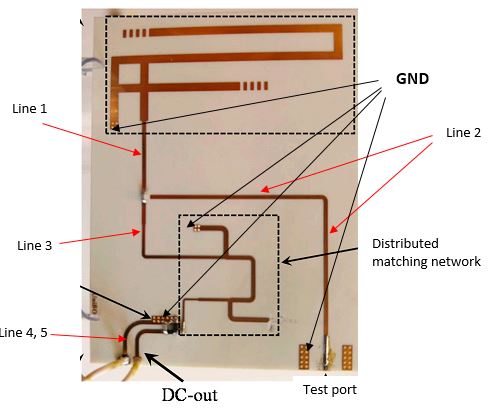
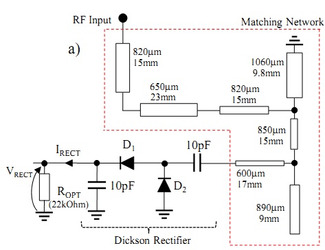
I'm designing a rectenna for harvesting power from UHF band. I've found a paper describing somehow in details of designing such a rectenna. The first image is the prototype rectenna, while the 2nd one is the matching network. The frequency is 868MHz. My questions are:
1. The traces numbered 1 to 5, especially trace 2 which connects the antenna to the test port, will have to be designed to have 50 ohm impedance? This was not mentioned in the paper, so I guess it is implicitly understood.
2. How can these GNDs be connected without any wire between them? Does it make any difference if I put traces between them? Do these trace have to be designed with a 50ohm impedance?
I can understand how to design an antenna using software (HFSS in my case). However I still don't understand the traces connected the antenna to other components such as the matching network, the IC or even the GND layer. How I can optimize them for the best performance is what I'm studying. So, any suggestion is highly appreciated. Thank you for your time ahead.