Designing an LC delay line
Hi,
the problem is the missing specification.
Thus numerous solutions are possible.
An example:
An LC filter beyond resonant has a phase shift of 180°.
Now let these 180° be 500ns.
--> So make the input frequency a sinewave with 1MHz. The first requirement is fulfilled. (delay of 500ns)
Now just specify an output voltage of 10V peak (it still is sine waveform), and specifiy the thresholds to be -1.571V and +1.571V.
--> The rise time between these two points is 50ns. And the second requirement is fulfilled.
Klaus
I should have added I'm looking to a delay a square pulse with a 5ns risetime and maintain a true risetime of 50ns. True risetime is simply sqrt(t_ro^2 - t_ri^2) where t_ro is the output risetime and t_ri is the input risetime. For a t_ri of 5ns, t_ro must be around 50ns.
I would expect a LC chain of may be 20 + 20 elements.
The LC ladder below is modified from the circuit in the menu of Falstad's animated interactive simulator. Free to download and use:
www.falstad.com/circuit
As the simulator is animated, it is striking to observe how the initial pulse causes current to travel in looping fashion from one stage to the next. The bucket brigade action is hypnotizing to watch.
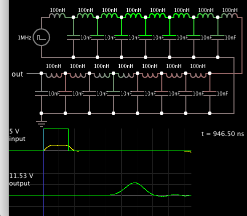
Values need to be adjusted to obtain your desired performance. To make 1000 ohm impedance, no doubt it needs more stages.
- Designing split ring resonator
- Which transistor need to be chosen for designing KU-Band LNA Design high gain, low NF
- Questions about S22 calculation of frequency tripler in ads simulation
- MC145151/2 p2 calculation dip swich vs xtal divader
- How to calculate bandwidth for this circuit, including lower and higher cut off freq
- Re: Calculate Capacitance Value from Smith Chart