RF Energy Harvesting Power Source
I'm trying to design a rf energy harvesting circuit specifically at the wifi frequency of 2.4GHz in TSMC 65nm. The circuit design is a rectifier with a differential input. My question would be on the test bench of the circuit. Is it possible to only use a voltage sinusoidal source for modelling the input rf signal? Is it correct that I need to simulate both transient and harmonic balance to test out the design? If so, can I use a port instance as the power source for both analyses?
Thank you so much for your help and time.
No.
See followings.
https://www.edaboard.com/showthread.php?378145
https://www.edaboard.com/showthread.php?379588
Yes.
Yes for non-modulated signal drive.
Thank you so much for your replies. If it is okay, I have additional questions.
Do you mean that I should assume a non-modulated signal drive for the wifi signal input for the rectifier since I only need the power delivered?
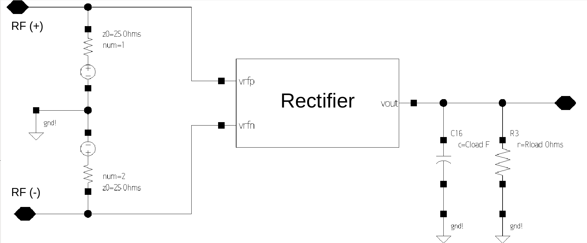
Would this be a correct setup for the port power source?
Attachment 155810
I am currently testing on how to input the correct parameters (i.e dc value, ac magnitude, amplitude value) on the port instance setup above in synopsys custom designer such that it will provide my desired power input (i.e -10 dBm). To confirm if the parameters I set are correct, I would measure the votlage rms on the node of rf(+) and rf(-) above and compare it with the equivalent rms voltage of my desired power input at 50 ohms impedance using the calculator provided here:
https://www.random-science-tools.com...atts-volts.htm
Is this a correct assumption?
It seems the image wasn't attached properly. I've attached it here again:
No.
Even if averaged powers are same for modulated signal and non-modulated signal, outputs of rectifier are different for them.
So you can not know rectifier output for Wifi signal with non-modulated signal drive.
You have to learn and study peak-factor of signal.
Can you understand differential drive ?
Do you think whether you do differential drive ?
Show me netlist.
Can you understand "power" ?
What power do you want to evaluate ?
Available Power ?
Input Power to Rectifier ?
Can you understand signal source impedance, input impedance of rectifier and impedance matching between them ?
https://www.edaboard.com/showthread.php?360833
I believe the most serious uncertainty factor involved with your energy harvesting application is the unknown field strength. You need to refer to assumptions.
Modulation can be considered by pulsing a sine source with a certain duty cycle.
I see. Thank you.
The rectifier I am trying to design has a differential input with cross-coupled configuration.
I am trying to evaluate the Input Power to the rectifier.
I have not yet considered the input impedance of the rectifier and the matching between source and rectifier since I am still in the rectifier design stage. I am assuming a 50 ohm port instance to represent the antenna for the rectifier test bench simulation.
Thank you for your replies. If it is okay, I have additional questions.
For now I am assuming a signal strength of less than -10dBm as input to my rectifier since I have yet to connect the antenna.
Does this mean I should be using a vpulse input instance in the schematic test bench instead?
Show me netlist.
I don't think your setting is for differential drive.
It seems you can not understand power definition at all.
If you don't know input impedance of rectifier, you can not know input power by only voltage.
You have to know both current and voltage for evaluation of power.
Surely see and understand https://www.edaboard.com/showthread.php?360833
No.
If your RF signal is ASK signal, ASK signal is available as multiplication of sinusoidal and vpulse.
And such ideal ASK signal is a little helpful with adjusting duty cycle.
However Wifi signal is not ASK signal.
So there is no duty cycle.
Can you understand Wifi signal ?
Surely see and understand.
https://www.edaboard.com/showthread.php?378145
It's complex modulated signal with several 10 MHz bandwidth, and it's pulsed. The envelope is roughly rectangular but with a widely varying duty cycle depending on the data flow.