Importing .dxf from HFSS to ADS
I need some guidance to import .dxf file (which i extracted from HFSS) to ADS. I read few previous post but could not get the solution to my problem.
The .dxf file that I get form HFSS is attached. I am really not sure if I extracted it correctly as its just 19KB and does not seem to have layer information.
This is a symmetrical octagonal inductor with 2 metal layers, oxide,substrate etc...
How I extracted this file was to go to MODELER->EXPORT FILE-> AUTOCAD(.dxf) option. Is this correct way to extract?
Now when I open ADS layout window and try to import. I get the error that "layer file does not exist". Well, I dont have the layer file with me.
Do I need to create it from ADS and if yes then how?
Is this a good idea of exporting from HFSS to ADS?
Please guide me, I am stuck here
Thanks a lot for your time..
Hemanshu
Please help me out here...
Before going to the DXF import dialog, go to Options > Layer in the layout editor menu. This will bring up the layer editor.
Go to the Advanced page and define the names of the DXF layers in your file.
Finally, save the settings into a file, with the default filename <projectname>.lay
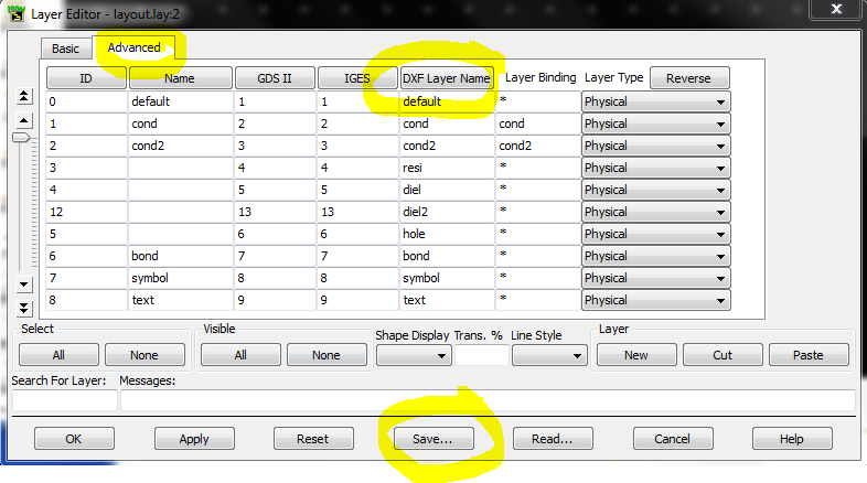
Now, you can use the DXF import.
Hi Volker,
Thanks for your help. I did exactly as you said. Now i am able to import the .dxf from HFSS but I get the following error message:
"Warnings occurred during DXF/DWG file load:
Using layers file "layout_new.lay".
UNKNOWN LAYER(S) FOUND IN INPUT FILE. Copying layout_new.lay to a new layer file: layout_new1.lay.
Adding layer number 39. Data was imported on layer Design_21 but this layer is
not defined in "layout_new1.lay".
Failed to create new design for "C:\Users\habbey1\layout_1_prj\networks\Design _21" because the design is currently open.
The open design will be used for the import. To avoid this warning message in the future close all designs before performing an import.
Import Complete"
I have defined the substrate layers in ADS. ( Please see the attached ADS project file ADS_prj). The top layer shape as I see in HFSS remains same but I cannot see its thickness or the
second metal layer. It looks like the importing has still some issues.
I am also attaching HFSS project file for your reference. ( DESIGN_21_HFSS).
Can you please guide me what I should do in HFSS or in ADS to see exactly the same kind of geometrical model as I see in HFSS?
Thanks a lot for your help.
Waiting for your reply
Regards,
Hemanshu Abbey
Hello,
I am working for Sonnet, so I do not have access to HFSS and can not check your files.
From the messages that you have shown, it seems that HFSS has created DXF layers that are not mapped in your ADS layer settings (e.g. "Design_21"). To find out what layers are created, and what their names are, you can use some DXF viewer software or AutoCAD, or you can ask Ansoft support what their software creates on export.
Regards
Volker
Hey Volker,
Yes you are right, When I extract .dxf from HFSS I only see single layer information. I don't even see the thickness of the first layer extracted out of HFSS. I have already contacted ANSYS and waiting to get access to the concerned technical support.
Requesting other readers to guide me for export from HFSS for a spiral inductor
Meanwhile I was thinking that in worst case if I have to redraw the same octagonal geometry in ADS momentum then how I would do that. I explored path and
polygon function in ADS but was not sure how I can create the attached (octagonal_top.jpg) geometry. What I was doing in HFSS was to draw a polyline and
draw a rectangle at its orgin and then just "sweep the path" so that my polygon gets completed. But in ADS the DRAW POLYGON fucntion creates a solid filled
geometry and the PATH function by default starts from the middle of specified co-ordinate ( this ruins my calculation for predicting coordinates)
What I want to do in Momentum is to draw the shape as specified in the octagonal_top.jpg. I want to have the ability to draw a ployline and then specify the thickness of it. Is this possible?
Volker, I really appreciate your help and time on this. Please guide me on this.
Thanks again
Requesting other readers to share their thoughts on this.
Regards,
Hemanshu Abbey
That's expected. Although the DXF file format would support z position and extrusion height, most tools only evaluate the x-y data. The z position and metal height must be assigned manually.
Oh ok...
So I take the info from the dxf and import to ADS and manually assign the thickness. Since you said you dont have access to HFSS I am not sure I should ask this
but what do you suggest me when I want to take the information of 2nd metal layer ( underpass one) from HFSS? Please find the dxf file attached in the zip folder.
So again, my problem was that I was only able to extract top layer(without thickness) from HFSS. The underpass or the 2nd metal layer info is not accessible its
structure is not replicated during transfer from HFSS to ADS.
Hello again,
I can confirm that the underpass is not included in the DXF file. Not sure what went wrong, because I am not familiar with the DXF output in HFSS. For the EM solvers that I use, you would have multiple layers in the DXF file, but your file has only that layer design_21. And although there are multiple shapes on layer design_21, the underpass is missing.
Given that you have the underpass layout in the HFSS file, I would contact Ansys support. It must be possible to include that in the output file on a separate layer (or perhaps in a different file, if for some reason they have implemented separate files for each layer).
For the trace with width in ADS layout, I don't know. My inductor layouts are auto-generated by an inductor shape generator, so that I don't have to draw them manually.
Hi Volker,
Thanks for your reply...
Yes you are correct, the underpass info is missing for some reason. I am waiting for ANSYS support
For the octagonal inductor layour in ADS I will post a new topic in case somebody has drawn it manually...
Thanks for all the support :)
Hemanshu