Using HFSS to simulate TSV-TSV coupling in 3D ICs
时间:03-30
整理:3721RD
点击:
Hello,
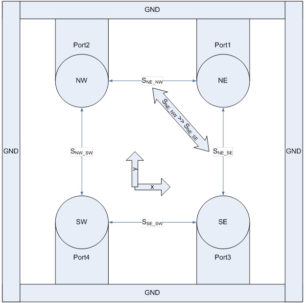
I am trying to simulate coupling between TSVs in 3D ICs for my Ph.D. research at UMD College Park. I have set up a simulation where 4 TSVs are placed in a 2x2 grid structure. A metal ring surrounds the TSVs, and is used as the ground reference. I would expect the coupling (S-parameter) from the North-East (NE) corner TSV to the North-West (NW) corner TSV to be the same as the coupling from NE corner TSV to South-East (SE) corner TSV. I expect this because the structure is symmetrical across both the x and the y axis. But the coupling from NE to NW is much greater than the coupling from NE to SE. I believe this is due to the fact that all my ports connecting TSVs to the ground ring are running parallel to the y axis. In other words I think that the ports themselves are coupling to one another, as if they were metal wires. This conjecture is supported by the fact that if I rotate all my ports to run parallel to the x axis, then the coupling from NE to SE is much greater than the coupling from NE to NW. See attached figure for clarification.
So my questions are:
1) Do ports couple to one another as if they were metal wires?
2) If not, then can you comment on the behavior I am observing, because I expect the coupling from NE to NW to be the same as the coupling from NE to SE.
3) If ports do couple to one another, then what is the correct setup for my experiment? I would like to be able to measure the coupling between TSVs independent of the size and shape of my ports.
Thank you in advance for your response.
Sincerely,
Caleb Serafy