HFSS cosimulation trick question
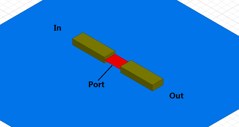
Here is an example: it is for cosimulation. Assume you have a structure, and a lumped Cap has to be put in between. So, we use lumped port(from metal to ground, internal port)
Case 1 - Single port
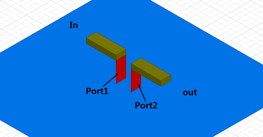
Case 2 - Double port
Cosimulation setup for case 1 and 2:
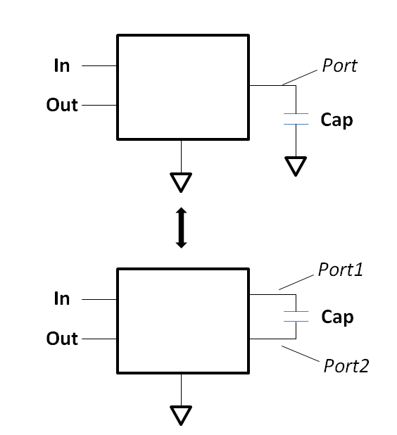
And they are equivalent! So can anyone pro on EM explain this?
Thanks everyone, I learned a lot from this awesome forum!
- - - Updated - - -
What is the math behind this? Anyone give me a link for further reading maybe?
Yes, if the component has only a series branch and i(1)=-i(2).
In the general case, with a component that has series and shunt current, the two port solution is used.
In both cases, to get accurate results, you will need to perform some de-embedding and remove the intrinsic inductance of the ports.
Thanks for the reply. It makes sense to me from current perspective. But how about the ground. Why do we need to connect 1port to ground? There is actually no current floating to ground.
As I wrote above: when you connect a component that has shunt elements, the currents in port 1 and 2 are different and then you need that ground return path.
Still like a magic to me. Thanks again.
Sorry, I think I misunderstood what is confusing you, and will try again.
To understand the port connection, let's review some basics. The most important thing to understand is that each port has two terminals, signal (+) and reference (-). In many cases, the reference terminals are connected to some metal that we use as global ground. However, ports can be modelled with different, independent grounds. In this case, current can only flow if grounds are somehow connected. The easiest way to understand this is if you think of where the current (signal and return) flows.
For the 1-port, the port is connected between two polygons. One polygon is connected to port 1 (+) and the other polygon is connected to port 1 (-). The terminal port 1 (-) is not connected to the metal below. If we short port 1, this means that we connect port 1 (+) and port 1 (-). This would be a connection between the two feedlines. Shorting port 1 does not create any current flow to the metal plane below, because the port reference is connected in a different place.
Now if we want to connect a series element instead of just shorting port 1, it is the same thing: we connect that series element in the circuit simulator between port 1 (+) and port 1 (-). This is what the image below shows.

It looks as if the component is connected to global ground, because the S-parameter block does not show individual grounds for each port. However, it is already implied in the concept of S-parameters that a load at port 1 is connected between port (1) + and port 1 (-).
Thanks volker for enlightening me with such detailed explanation. Now I can understand the theory behind this.
I think the key is not to treat the ground reference as traditional 'same voltage plane'. Instead, think of the ground more from scattering parameter perspective.