Edge-coupled passband filter with CST
I'm simulating a edge-coupled microstrip passband filter on 1.0mm alumina substrate with relative permittivity 9.9. I designed the filter and it's working just fine, I have almost exactly the desired frequency response. My problem is that in the final design i'm supposed to feed the filter with a 50ohm coax. I started off by just assigning a port straight to the first microstrip line thinking that I can change the feeding mechanism to a coax once i've got the desired response. Well, it turns out i'm not able to do it as easily as i had hoped. I thought id would be simple as i'm quite sure i've fed microstrip lines with coax's before by just simply connecting the center connector (used PEC) of the coax to the microstrip line. The desired passband is 5.9-6.1 GHz. I tested the coax's (I tried both air-filled and dielectric-filled) and they worked fine and had 50ohm impedance. What am I missing here?
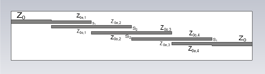
Picture of the structure is attached. Z0 line is 1.2mm wide and thickness is 0.035mm. Material is PEC.
Thanks
What exactly is the problem?
You mention that "i'm not able to do it as easily as i had hoped"... why not? What you're suggesting sounds entirely reasonable - connecting the centre conductor of the coax to the PEC microstrip line should certainly be OK.
Nice filter, btw :)
I thought it was reasonable as well. I tried it again and there just seems to be no coupling from coax to the microstrip line. I changed the structure a bit and now did it the same way as in here: https://www.edaboard.com/thread265445.html#post1138739
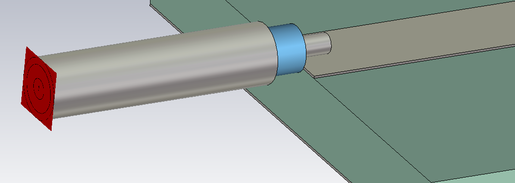
But no success. Here's a picture of my coax. Light blue part is vacuum and other parts are PEC.
I again tested the coax on its own and it's working just fine
Thanks :)
Of course, you must connect the coax shield (ground) to your filter's ground.
Thanks for the reply.
Could you explain how I should do that? I've simulated coax-fed microstrips before but can't remember much and tbh they were more or less step-by-step type of exercises. I've tried googling but I haven't been able to find any projects or reports that would describe this kind of feeding either.
Would it work better / be easier if I fed the resonator from below through the ground plane?
edit: okay feeding through the ground plane seems to be working. Just did a small test simulation, gonna try it with my filter next
If you want to include the coax feed, try to make the ground connection similar to the ground connection in your measured hardware.
Actually the task was to just design and simulate a filter which would have a pre-defined frequency response, so no actual hardware is involved. But it's working perfectly now when i'm feeding it through the ground plane.
Thanks for the help both of you!
If the coax transition is not known yet, you should remove it from the simulation model. It makes no sense to model an unrealistic coax freed from the backside. Modellig with planar feed is more accurate/more correct in this case.
Yeah I'm aware of that and thought it was unnecessary as well but for some reason the instructions insisted that coax feed should be used.
- Looking for SPICE model for coupled lossy transmission line
- capacitivity coupled coil simulation in HFSS A 1MHz
- Why pick Hairpin over Edge-coupled Bandpass Filter?
- Re: capacitivity coupled coil simulation in HFSS A 1MHz
- Coupled Mode Theory for Wireless Power Transfer
- [moved] apperture coupled feeding in microstrip stacked patch antenna in ads