Why is a Signal Conductor required for TEM mode in 3D Finite Element Software Package
时间:03-30
整理:3721RD
点击:
Hello fellow Emag bandits
I am using an EM simulation software package called HFWorks.It is an 3D FEM package and is an add on to the SolidWorks CAD software.
When doing a simulation of,for example,a coax fed half wave dipole,the model requires that a SIGNAL boundary condition be applied to some part of the model whenever the mode of the waveport excitation is TEM or the port is a lumped port.For instance, the coaxial cable feed could be modeled as just the dielectric with a SIGNAL boundary condition placed on the inside surface where the central conductor would go, and a PEC (Perfect Electrical Conductor) boundary condition placed on the outside surface to represent the ground or the return conductor. The same boundary conditions would be placed if the coax was fed with a lumped port with a defined impedance.
Why does the software need to distinguish between two different conductors, with one as SIGNAL and the other as ground or return, only on the cases when the wave port is excited with the TEM mode or the structure is fed with a lumped port.Why is this not the case for a structure such as a waveguide or microstrip.
Let me know if more detail or information is required.Any input would be appreciated.
Thanks
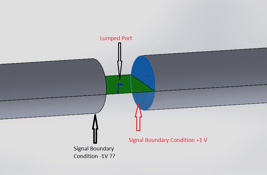
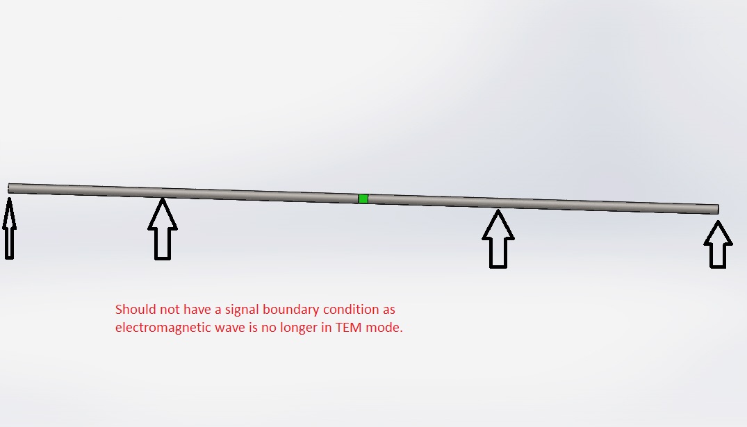
I have another related question. When defining a SIGNAL boundary condition, you have the ability to specify the voltage, which can be positive or negative. This is so that one can excite differential or common modes in a structure...apparently. So If I was modeling a thin wire half wave dipole fed at its center with a lumped port, would I need to specify one conductor to have a SIGNAL boundary condition with a positive voltage (+1V) and the other to have a SIGNAL boundary condition with a negative voltage(-1V), or would it be defined as a ground conductor instead. Hopefully the photos provide some more clarification.
I am using an EM simulation software package called HFWorks.It is an 3D FEM package and is an add on to the SolidWorks CAD software.
When doing a simulation of,for example,a coax fed half wave dipole,the model requires that a SIGNAL boundary condition be applied to some part of the model whenever the mode of the waveport excitation is TEM or the port is a lumped port.For instance, the coaxial cable feed could be modeled as just the dielectric with a SIGNAL boundary condition placed on the inside surface where the central conductor would go, and a PEC (Perfect Electrical Conductor) boundary condition placed on the outside surface to represent the ground or the return conductor. The same boundary conditions would be placed if the coax was fed with a lumped port with a defined impedance.
Why does the software need to distinguish between two different conductors, with one as SIGNAL and the other as ground or return, only on the cases when the wave port is excited with the TEM mode or the structure is fed with a lumped port.Why is this not the case for a structure such as a waveguide or microstrip.
Let me know if more detail or information is required.Any input would be appreciated.
Thanks
I have another related question. When defining a SIGNAL boundary condition, you have the ability to specify the voltage, which can be positive or negative. This is so that one can excite differential or common modes in a structure...apparently. So If I was modeling a thin wire half wave dipole fed at its center with a lumped port, would I need to specify one conductor to have a SIGNAL boundary condition with a positive voltage (+1V) and the other to have a SIGNAL boundary condition with a negative voltage(-1V), or would it be defined as a ground conductor instead. Hopefully the photos provide some more clarification.
- Required help in simulation of Ungrounded CPW Structure in HFSS
- Required HFSS Simuation FILE (split ring resonator)
- [moved] guidence is required for phased array
- how to create required plots in HFSS
- [Help Required]HFSS Simulation of UWB Antenna Doesn't Tally With Desired Results
- HELP required in EBG substrates..