how to analyze the S parameter when you simulate a transformer in momentum?
![]()
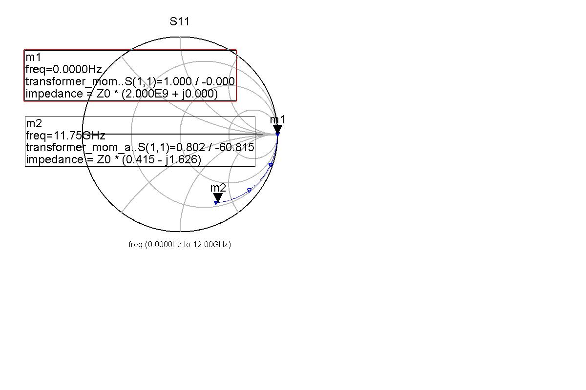
I think the impedance from S11 means Z11. Why the real part of Z11 is so large(2.000E9) when frequenz zero? Why the imaginary part of Z11 is negtive(-j1.626)? Does anybody know how to analyze the S parameter? can you tell me the layout of the transformer right or wrong? Does anybody have a project about transformer simulation in momentum?
thanks!
Something is completely wrong. Maybe missing ground reference.
I agree. The 3D view of the EM model looks ok, but there must be some gap (open circuit) in your metal path.
can you tell me how to add the ground reference? can you check my project? I have attached the momentum project here, including the GDSfile, streammap file and the substrate file.
Help me!
can you tell me how to add the ground reference? can you check my project? I have attached the momentum project here, including the GDSfile, streammap file and the substrate file.
Help me!
Why don't you do it yourself, to learn more about ADS and your model? This is your project.
The problem is the metal path from port to inductor to ground isn't complete. There must be a gap, or one of the metal properties is wrong. The curve that you see is the parasitic shunt capacitor to the substrate.
I have checked my project.
there is a gap!
thank FvM and volker@muehlhaus.
I think I have solved my problem:
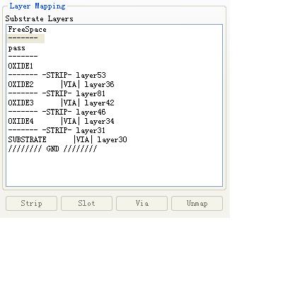
substrate file:
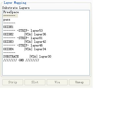
modified substrate file
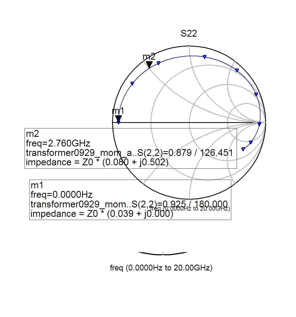
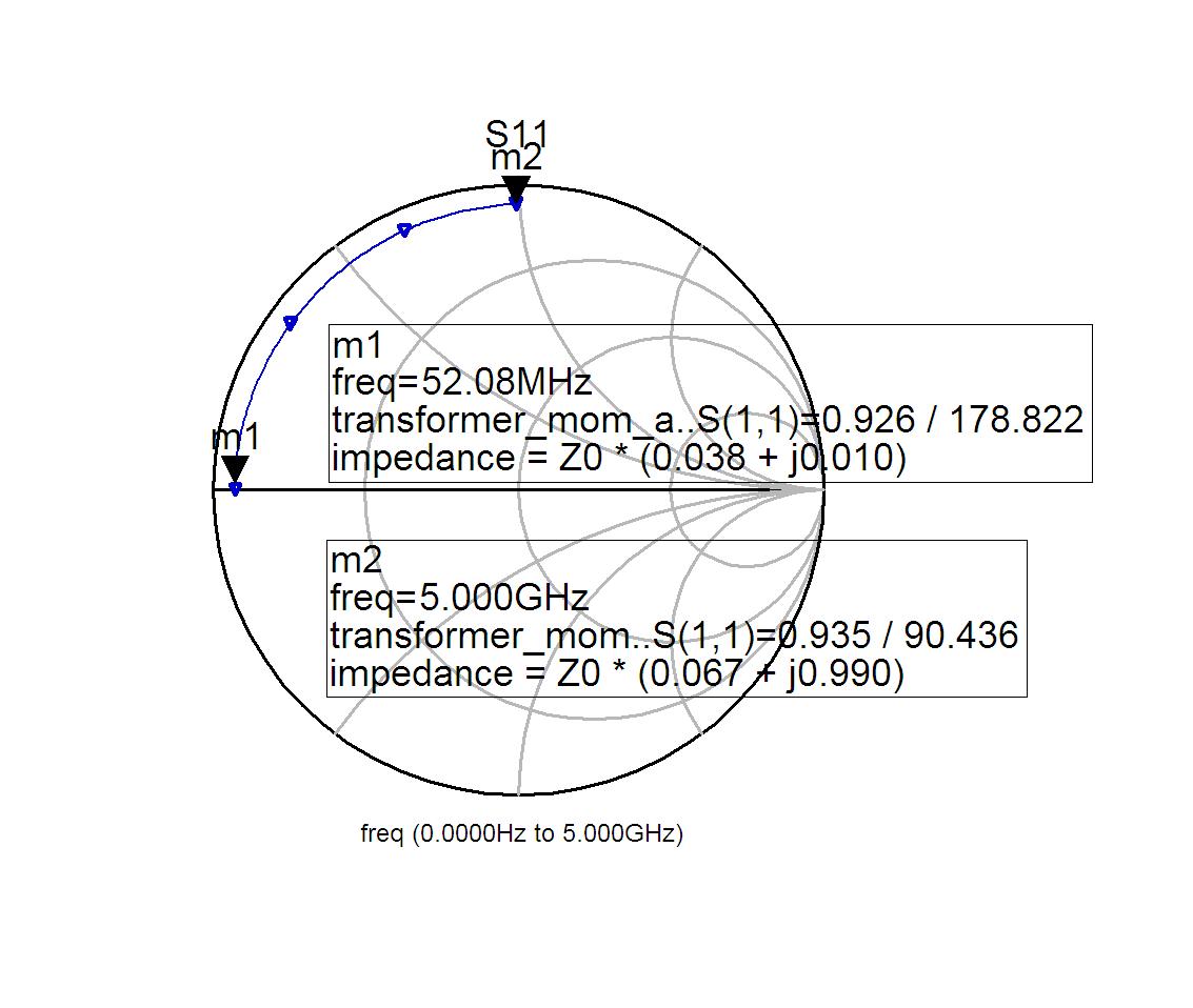
simulation results of the primary coil:
can you tell me I am right or not? can you tell me some better way to solve this problem?
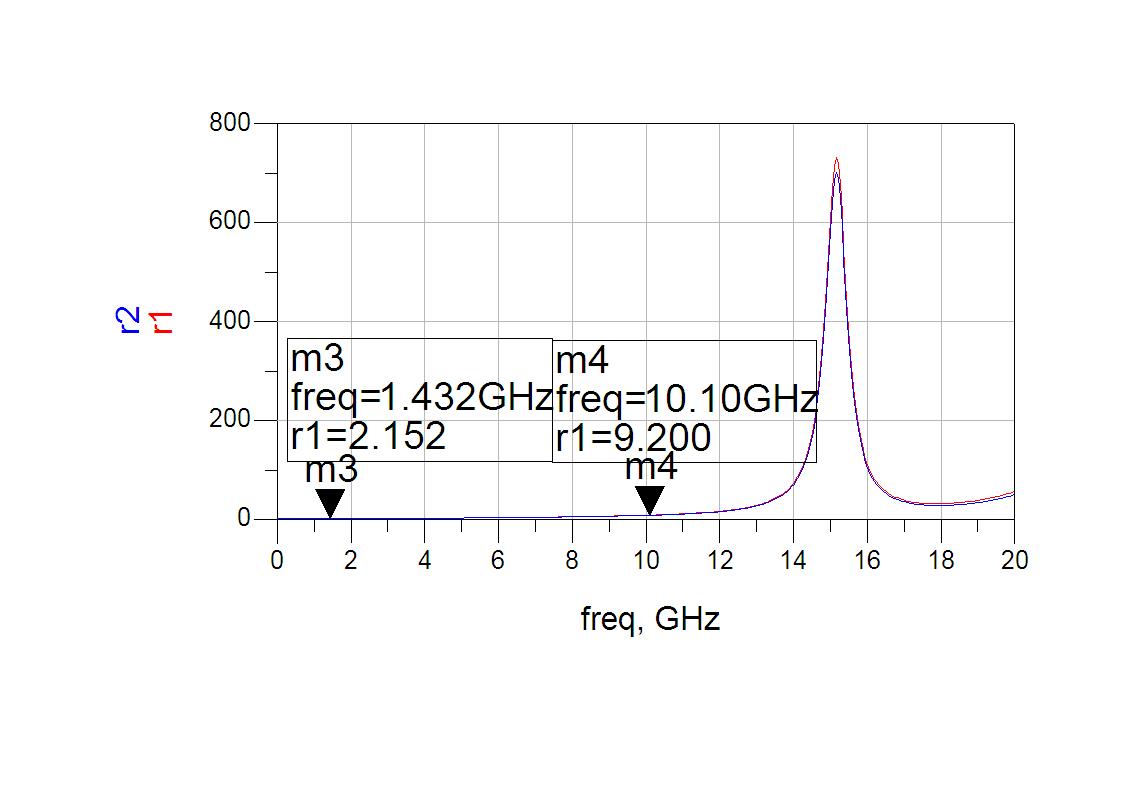
The resistance at low frequency is 0.038 * 50 Ohm = 1.9 Ohm now. This makes sense for the series resistance of your transformer coil.
Other equations that will be useful for transformer evaluation in the ADS data display:
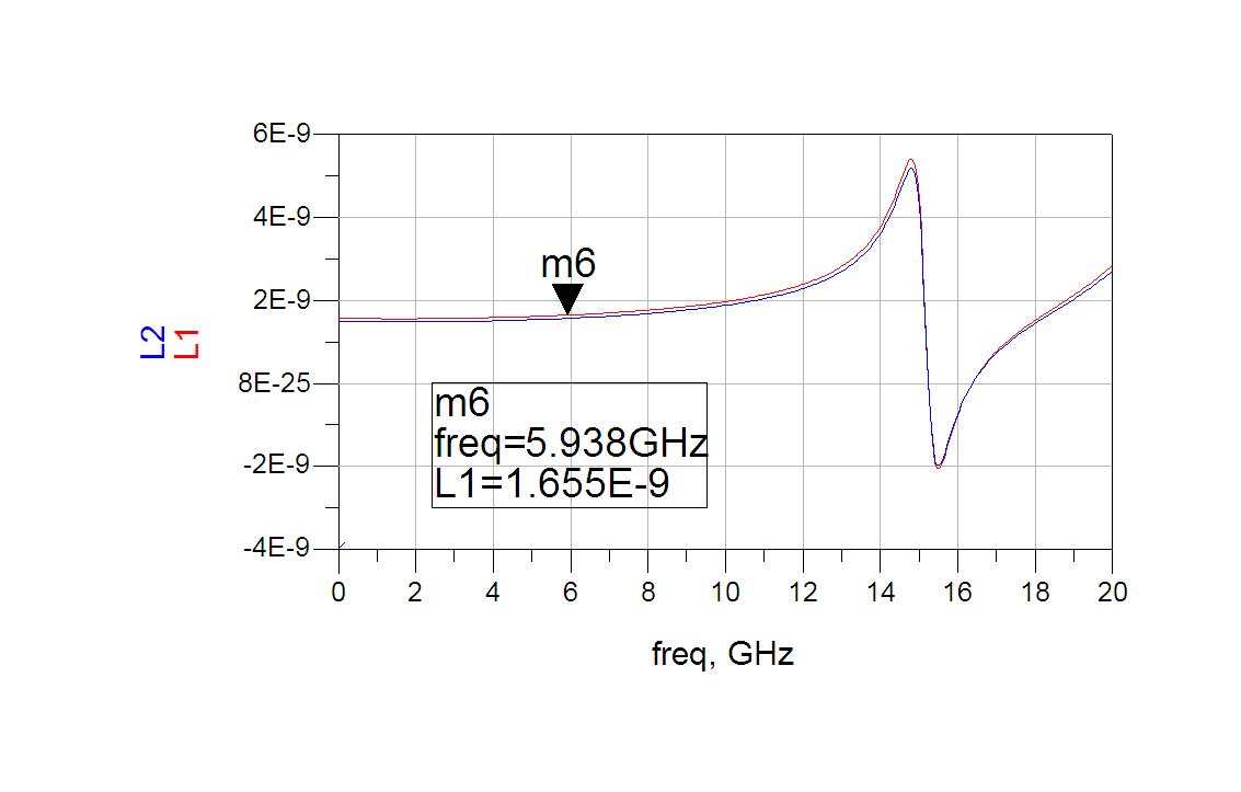
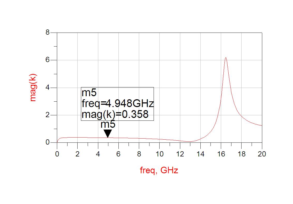
Inductance of primary/secondary and coupling factor k:
Z = stoz(S)
Y = stoy(S)
omega = indep(S) * 2 * pi
L1 = imag(Z11) / omega
L2 = imag(Z22) / omega
k=sqrt(1-1/(Z11*Y11))