HFSS-ADS Co-simulation Problem
In HFSS, the antenna is treated as a two-port network, one port (Port1) for excitation, and the other (Port2) for negative capacitor placement. After HFSS simulation, the S2P file was extracted and imported into ADS.
In ADS, the excitation port (Port1) was connected to 50 ohms Term, but how to connect the lumped capacitor to the other port (Port2)? Should I just place it between the Port2 and ground?
Yes, place the load between port 2 of the S2P block and ground. This means it is connected between (+) and (-) of the HFSS model port 2.
Thank you very much!
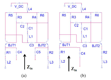
However, in which way should I connect the following two circuits to the S2P block. Figure(a) is a floating-type negative impedance converter, while Figure(b) is a grounded-type negative impedance converter.
For grounded one, it is apparent that we could connect the input pin (in front of capacitor C4) to the port2 of S2P block, and connect the "ref" port of S2P block to ground.
For floating one, if we connect the left pin (in front of capacitor C4) to the port2 of S2P block, and the right pin (in front of capacitor C5), and the "ref" port of S2P block to ground, it seems the floating circuit was turned into a grounded one. Could I connect the two pins of floating one to port2 and 'ref' ports of S2P block respectively?

Yes.
This is a common misunderstanding when using EM ports with different (local) grounds. You need to understand that current from the (+) terminal of the EM port will always return to the (-) terminal of that port, and not to any other ground. Or in other words: if you connect an impedance in ADS to ground, that impedance is connected between the (+) terminal and the (-) terminal of that port. Even though it seems that different grounds are connected at schematic level, they are not. They are only connected via ground if that ground path connection physically exists in the EM model (e.g. multiple ports all connected to the same ground in EM model).
So floating or grounded, your active circuit represent an input impedance and that must be connected between the S2P pin 2 and the S2P ground reference => impedance is connected between (+) and (-) of the EM model.
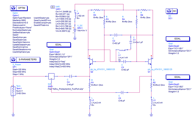
By saying that the active circuit must be connected between S2P pin 2 and the S2P ground reference, do you mean like the connection in figure below where floating circuit is used?

The difficulty here is that your Term1 ground is not connected to the S2P ground reference.
If you make that change, and connect the Term1 ground reference to the S2P ground reference instead of the ground symbol, then I think it will work.
