Untheoretical Frequency Change
The first patch should be at 2.4GHz and then the first + second patch should be 2.1GHz.
Theoretically the frequency should decrease from 2.4 to 2.1GHz when the second patch turns on (I.e when the length of patch gets longer).
However the frequency actually increases!
How can I fix this?
show work done with controlled impedances and tolerance
Is this a verified method/layout?
To me, that patch "extension" idea looks wrong. The current path/pattern is totally different from the current in a patch antenna.
How have you configured your microstrip , stubs and slots for polarization and reactive loading?
Have you considered linear and circular polarization with two near-degenerate orthogonal resonant modes with equal amplitudes and a 90◦ phase difference?
Is it because of the way I have tried to connect both patches with a transmission line in between?
What is the proper way to extend?
Yes.
There are some dual band patch antennas in literature -> check
Ah ok. Thank you for your helpful replies! :)
I have checked online about dual band patch antenna and found one similar to what I want to do:
http://slidegur.com/doc/335663/recon...nna-powerpoint
However it does not show what the current path should look like.
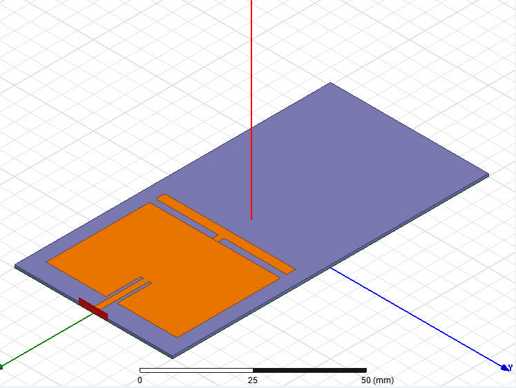
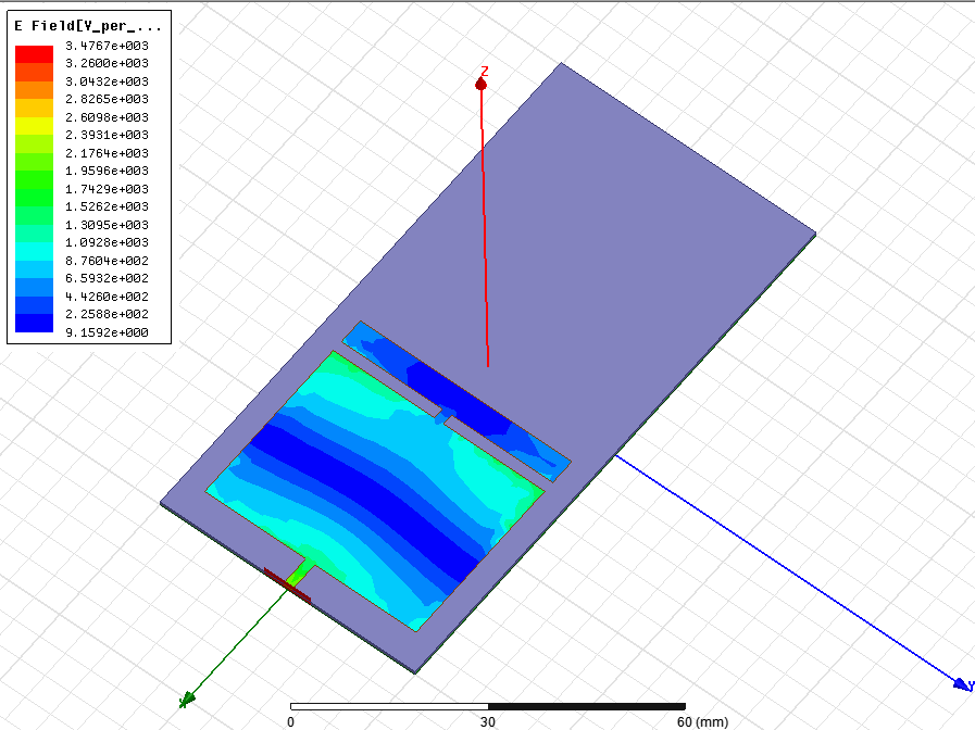
This is the current path of my patch model.
What could be improved about the connection to get it looking normal so the frequency will decrease?
The big difference between your antenna and the paper is that
- your antenna has a single connection to the extension in the center, not many distributed, and
- your antenna does not switch that patch extension on/off.
Oh, ok...
I changed the design to this so that the extension is distributed.
The transmission line represents a switch (pin diode) to turn the patch extension on.
But the frequency is still increased instead of decreasing?

You started with a resonance at 2.4GHz, and the frequency has moved down to 1.8GHz in your plot. This is what we expect.
For the field plot, resonance frequency gives more information than plotting at 2.4GHz (where you have no resonance with these dimensions).
Untheoretical Frequency Change 相关文章: