[Moved]: Verilog-A model for generating a waveform
时间:03-30
整理:3721RD
点击:
Hello,
I want to generate a 5% duty cycle clock using verilog-A model with frequency of 5MHz.
can anyone help me with this?
I have written the code as attached. But it doesnt work.
I want to generate a 5% duty cycle clock using verilog-A model with frequency of 5MHz.
can anyone help me with this?
I have written the code as attached. But it doesnt work.
Show your verilog-a code by text, so that I can modify it.
Code Verilog - [expand]
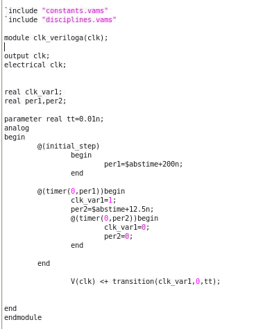
I could find a way to generate the non-50% duty cycle clock.
Below is the code and it works fine.
`include “constants.vams”
`include “disciplines.vams”
module clk_veriloga(clk);
output clk;
electrical clk;
real clk_var1,clk_var2;
integer clk_var3;
real per1;
parameter real tt=0.01n;
analog
begin
@(initial_step)
begin
per1=Sabstime+100n;
clk_var1=1;
end
@(timer(0,per1))begin
clk_var1=!clk_var1;
end
clk_var2=absdelay(clk_var1,87.5n);
clk_var3=clk_var1 && clk_var2;
V(clk) <+ transition(clk_var3,0,tt);
end
endmodule
Try the following
Code:
`include "constants.vams"
`include "disciplines.vams"

module vclock(PLUS, MINUS);
inout PLUS, MINUS;
electrical PLUS, MINUS;

parameter real delay = 0.0 from [0.0:inf); //Output Waveform Delay Time.
parameter real val0 = 0.0; //Zero Value used in Output Pulse Waveform.
parameter real val1 = 1.0; //One Value used in Output Pulse Waveform.
parameter real period = 100.0u from (0.0:inf); //Period of Input Waveform.
parameter integer ndiv = 1 from [1:inf); //Divide Ratio of Output Frequency.
parameter real rise = (ndiv*period) / 100.0 from (0.0:period);
//Rise Time for Output Pulse Waveform (Time for Transition from 'val0' to 'val1').
parameter real fall = (ndiv*period) / 100.0 from (0.0:period);
//Fall Time for Output Pulse Waveform (Time for Transition from 'val1' to 'val0').
parameter real duty = 0.5 from (0.0:1.0); //Duty Factor for Output Pulse Waveform.

/*
5 edgetype=linear   Type of the rising and falling edges.
This is for pulse waveform and pulse-like piecewise linear waveform.
Possible values are linear or halfsine.
*/

integer trigger;
real width; //Output Pulse Width (Duration of 'val1').
real period_1, duty_1, max_step;

analog begin
   @(initial_step) begin
      if(ndiv == 1) begin
         period_1 = period;
         duty_1 = duty;
      end
      else begin
         period_1 = ndiv * period;
         duty_1 = floor(ndiv/2) / ndiv;
      end

      Sdisplay("%M (Ndiv=%d, Duty_Factor=%.1f)\n", ndiv, duty_1);

      max_step = min(rise, fall);
      width = duty_1 * (period_1 - (rise + fall));
   end //initial_step

   Sbound_step(max_step);

   @( timer(delay, period_1) ) trigger = 1; //Generation of Rise Edge
   @( timer(delay+rise+width, period_1) ) trigger = 0; //Generation of Fall Edge

   V(PLUS, MINUS) <+ val0 + (val1-val0) * transition(trigger, 0.0, rise, fall);
end //analog

endmodule