[moved] How to define integration line for this antenna?
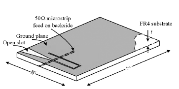
I would like to know how should I define the integration line for this kind of antenna ?
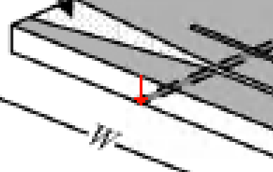
Is it ok to define the integration line as in the file "antenna with integration line.jpg" ( red line)? If not, then the arrow should be pointing in which way?

Thank you
I forgot to mention but I am using HFSS software. I would like to know in which direction the arrow (integration line) should be pointing?
i think your using lumped port excitation, in that case, the interation line is taken from the top conductor to the bottom conductor ( in this case your feed line)
Do you mean like in this attached picture ?
If I try to define like that, it tells me ¨Lines can only be created on select surfaces¨
It's like my integration line must be inside the excitation plane ( must be drawn inside that rectangle ).
Whenever I click outside of that rectangle it says ¨Lines can only be created on select surfaces¨
Does anyone know why and how I could solve this?
send me your file
I prefer to get explanations.
Yes, the line is between "signal" and "ground" of the port, usually the shortest possible path.
In your post #1 picture, you draw it on a feedline, that makes no sense.
Have a look here: http://hfss13.blogspot.de/2012/05/in...ion-lines.html