Calculate inductance of a coil in CST
How to feed the coil in order to get the inductance ?
It depends what configuration you are interested in, see
http://muehlhaus.com/support/ads-app...uctor-em-ports
If you want 1-port data with a lumped port between the ends of the turns, you should include the underpass (bridge), so that you have a clearly defined current path.
Hye,
If i'm using one port between ends of turns, how to find the inductance of the coil?
Convert S to Z-parameters
L = im{Z11} / (2*Π*f)
How to find the frequency response of the coil?
What exactly do you mean by "frequency response" ? Which parameter ?
You get frequency dependent S and Z parameters from simulation, so the calculated L from the above equation is also a function of frequency.
So...the inductance will change according the frequency? and how o find the Q factor of the coil in CST?
Yes, the effective inductance will change with frequency
Not sure how to calculate that in CST, but Q = imag{Z11} / real {Z11}, as described in my appnote linked above #2
If i simulate planar square coil in frequency range 10MHz-20MHz, which simulation tool of CST i should choose? MWS or EM?Because my simulation has 10 billion mesh size! Please help.
I use ADS with Momentum (Method of Moments) as the preferred solver, but FEM works as well.
I never tried the time domain solver for this type of problems. Time domain is a good choice for electrially large models, but inductors are electrically small. If you don't have MoM, I suggest you use the FEM solver.
I mean how to get resonant frequency of the coil?
I don't know what math CST offers you, but I evaluate the L(freq) curve to get the frequency where L changes from positive to negative value.
http://muehlhaus.com/wp-content/uplo...une_result.png
http://muehlhaus.com/wp-content/uplo...une_result.png[/QUOTE]
What software you use to get this results?How to use it?
This is RFIC Inductor Toolkit for ADS
http://muehlhaus.com/products/rfic-i...oolkit-for-ads
[QUOTE=volker@muehlhaus;1589183]Yes, the effective inductance will change with frequency
If the inductance will change with frequency, why in the formula inductance below does not include f parameter?
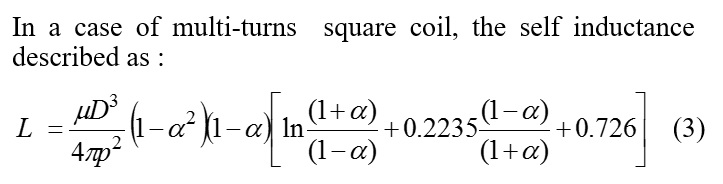
Any empirical formula involves a simplification. As long as Q is high, frequency dependency of inductance is low and can be usually ignored.
You need to understand ideal inductors vs. real physical inductors.
Your textbook equation calculates the DC (!) inductance value. At frequencies above DC, there are many influences that change the effective inductance: skin effect will cause a droop (!) in inductance, parasitic capacitances will result in an increase of effective inductance, peaking at SRF where effective inductance goes to infinity.
One comment on FvM: It really depends if the inductor is operating much below SRF. I have been working on EM analysis of PCB inductors and RFIC inductors for many years, and there have been only a few cases like RFID or wireless power transfer where inductance can be assumed constant because operating frequency is much below SRF.
Good luck anyway
Volker
you can use Ansys/Ansoft Maxwell for calculating inductance of the coil. here is the complete video, which will help you. You can get self inductance as well as mutual inductance between the coils.
https://www.youtube.com/watch?v=Ej4-er33Z3M
This video shows that How to calculate the self inductance and mutual inductance between the coil.
you can calculate it using Ansys/Ansoft Maxwell Software.
inductance Calculate CST 相关文章: