How to correctly calculate coil's field strength?
https://www.omnicalculator.com/physi...magnetic-field
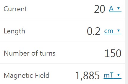
First of all this formula does not take into account the diameter of the coil. It is not the same if coil has 1cm radius or 10cm, of course, bigger the radius less flux density for same field strength.
Second and key point is that as we decrease the length of the coil field is supposedly getting proportionally stronger. For example, if we enter just 1 turn, current of 1mA but we decrease the thickness down to 1 millionth of a cm, that is, 0,0000001 cm, we supposedly get a field of ~1,25T.
Now, we sure don't expect that such miscroscopic coil would extend it's field anywhere outside it's microscopic dimensions. It might be 1.25T but only on the microsopic level which is not implicated by this formula.
I am asking cause i am trying to make a 0.4T or stronger field inside a 4cm diameter air core coil. But with this formula as only reference i can't be sure of best combination.
For example if i take 25 meters of 1mm thick wire and wind 50 turns of it all in one level and push 20A into it, according to the formula, field strength in the center of the coil will be ~1.3T.
I am highly skeptical that this is realistic, again maybe it is on a minute scale if coil radius is very very small.
My intuition tells me to use 100 meters of 2mm wire all wound in same plane in Tesla bifilar fashion to get bit more juice out of it. I roughly estimate this would be ~150 turns.
According to formula above with 20A current, field in the center of this coil should be ~1.9T. But is it really?

What do you think/know.
The given simple field equation is valid for long solenoids, almost exactly for length >= 100*radius. There's also a simple equation for the field at the centre line of short (radius < length) and a slightly more complicated formula for medium length coils. See e.g. https://en.m.wikipedia.org/wiki/Solenoid
Field of a flat coil can be calculated by summing the contribution of each loop.
I assume you wanted to write "radius > length", not "radius < length", as i am talking about a flat coil where radius is bigger than length which is minimal (thickness of a wire).
Can you specify which simple formula for pancake coils you refer to, please.
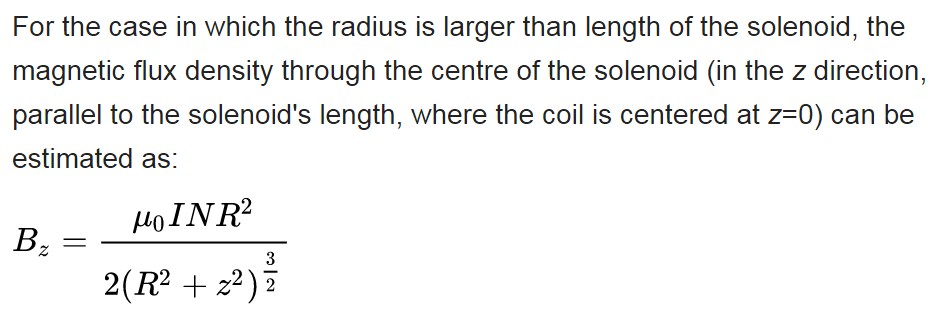
I assume you mean this one.

According to the text from where you took the above picture, the general formula seems rather this one:

Which is not for the average field, but the field at some specific radius z.
But why, the one i quoted clearly states it is for case "radius is larger than length of the solenoid" while the one below it is "For cases in which L and R are of a similar magnitude".
In case of flat coil, obviously, radius is larger than length, they are not similar.
This video tutorial just confirms the above formula as being the general case at any radius:
https://slideplayer.com/slide/9159072/
Refers to 00:35s to be more specific.
I believe you are more versed with math, could you please calculate what would be the field in the center if i used the following parameters.
Current: 20A
Wire thickness:2mm
Wire length: 100m
Number of turns: ~150
Inner diameter: 4cm
Core: none
Once again, if i go with 2mm thick wire i have 100 meters at disposal.
So, is it better if i go with
a) one layer, less length but also less turns (since each turn gets wider but lesser length)
b) 2 or more layers, more turns (since radius is less) but also more length
I want to calculate the field with that formula but i don't understand what z is.
Z is only mentioned in "where the coil is centered at z=0"...
I have found that for a single loop with radius R, the field is B=μ0I/(2R). Since my minimal radius is 4cm, it seems it might be better to go with 4 (or even 5 layers) and more turns solution than just 1 layer pancake coil. My goal is also to decrease the inductance which comes with bigger radius, but then again, more turns increases inductance so these two probably balance either way.
z is the distance from the coil center plane along the axis.
Before we discuss about suitable coil geometry, you should tell more clearly about the purpose of your design. For a short coil, maximum field strength is only achieved in the center point of the coil (r=0, z = 0). What's the working volume where you want to achieve a certain field strength? How uniform?
Like i said i need 0.4T or more in the CENTER of the coil.
At the moment i am waiting for a PS which will be able to deliver 20A into 2Ohm at 48V.
Amount of copper is arbitrary. Last few months i been trying to get flat copper wire from China and India but no one wants to see small amounts, so i am stuck with round wire.
I have again calculated resistance using this calculator
https://chemandy.com/calculators/rou...calculator.htm
and i am thinking 100m of 1mm thick wire which is ~2Ohm, but if you think i should rather go with thicker and longer wire, please suggest so.
Please take into account I'll wind in Tesla bifilar fashion so i should get 20-30% more field than calculation predicts.
Example of Tesla bifilar field gain.
https://www.youtube.com/watch?v=PxcS0oYsBG4
The center of the coil is just a point. My question was about the operating volume, let's say a Zylinder of radius r1 and height h where the axial field strength doesn't drop below a certain values.
20A into 2 ohms means 800W power dissipation, the heat of a small cooking plate.
Tesla bifilar configuration as I know it has some effects on self capacitance but absolute none on DC field strength. https://en.wikipedia.org/wiki/Bifilar_coil
I repeat again field must be inside the 4cm inner diameter of the coil. Volume doesn't really matter. How uniform? I'm not sure what you mean, clearly it cannot be perfectly uniform if we look at lines of force inside such coil. So as uniform as it gets.

Field must be 0.4T or more in that center region 4cm wide and let's say 1cm high.
I know it's big power dissipation, that's why i'm asking, considering options.
Why do you say "absolute none on DC field strength" when i just posted a vid showing ~30% increase in field strength by using Tesla bifilar config.
No, you are saying this for the first time. You only told about 4 cm inner coil diameter, which can have many purposes, not about field distribution.
.
I believe my question was much more precise than your witty answer.
You are asking for an optimal coil form (diameter, length, number of layers) for a given wire length. The optimization problem can be solved if you give us a performance metric.
I don't recognize the video showing anything.
You may want to review Tesla's bifilar coil patent https://patentimages.storage.googlea...c/US512340.pdf
It doesn't make claims about field strength, only about relation of coil capacitance and inductance.
O.K., that can be used as a specification. Don't care about uniformity, only specify the minimal field strength. I may sound pedantic, but is the 0.4T field magnitude (any direction) or axial field strength?
I didn't define the height cause i am not asking about field distribution, just field strength in the center.
What i mean is that it doesn't matter if you confine the field vertically or not, same number of fluxlines must pass through the center, and that's what i'm interested in.
You gave no real answer.
I gave all parameters that are needed.
Video shows how field gets ~30% stronger when winding is in Tesla bifilar config, i don't know how you missed that.
Axial field strength.
Video claims, it doesn't show, small but important difference. If a video "shows" a new over-unity apparatus, do you believe?
I know however that the video's claim neither complies with physical law nor with Tesla's original idea.
Let's please just focus on what is the best configuration to achieve 0.4T field in the center of the coil with given parameters (or variants of them).
Could I suggest to be more practical and simply input such parameters in an online calculator and with a trial-and-error process find the value that suits you need? As mentioned earlier along this thread, the maximum value can be approximated by the formula shown at post #4, and the average value can be found by programs that are supposed to perform numerical integrations, such as this one:
https://preview.wolframalpha.com/cal...al-calculator/
Engineering is a science based on tolerance of values within a margin of error, and your specification has such flexibility, especially since it does not define how much more, so let's go.
I already tried a similar calculator for flat coil.
http://kaizerpowerelectronics.dk/cal...il-calculator/
You know that it is another geometry, whose formulae are distinctly different, so it is not clear how this fits into the case discussed so far, the coil.
Anyway, it may not have been clear that it is up to you to do the next step: Make experiments, tabulate results, and compare each case to determine which one suits your need. At least it is how I do.
