AP0100CS图像信号处理器操作之读写时序(独家整理)
AP0100CS集成了Aptina的先进图像处理管道(pipeline),具有令人惊叹的视频和低光照性能。借助用于宽动态范围图像再现(rendering)的高级局部色调映射(Advanced Local Tone Mapping, ALTM)功能,即使在非常困难的高对比度照明条件下也能够生成高质量的视频。AP0100CS集成了具有高级转换器功能的NTSC/PAL编码器,可以提供模拟CCTV市场所需的高TV线分辨率。
这款产品为中国市场设计人员提供了过去无法获取全新相机设计方案;也就是说,能够利用高端IP相机传感器的高分辨率、内在的卓越低光照性能及WDR能力,移植应用于模拟CCTV监控领域。这种强大的设计灵活性将会带来令人激动的新型监控摄像机。
典型操作
A typical READ or WRITE sequence begins by the master generating a start condition on the bus. After the start condition, the master sends the 8-bit slave address/data direction byte. The last bit indicates whether the request is for a READ or a WRITE, where a "0" indicates a WRITE and a "1" indicates a READ. If the address matches the address of the slave device, the slave device acknowledges receipt of the address by generating an acknowledge bit on the bus.
If the request was a WRITE, the master then transfers the 16-bit register address to which a WRITE will take place. This transfer takes place as two 8-bit sequences and the slave sends an acknowledge bit after each sequence to indicate that the byte has been received. The master will then transfer the 16-bit data, as two 8-bit sequences and the slave sends an acknowledge bit after each sequence to indicate that the byte has been received. The master stops writing by generating a (re)start or stop condition. If the request was a READ, the master sends the 8-bit write slave address/data direction byte and 16-bit register address, just as in the write request. The master then generates a (re)start condition and the 8-bit read slave address/data direction byte, and clocks out the register data, 8 bits at a time. The master generates an acknowledge bit after each 8- bit transfer. The data transfer is stopped when the master sends a no-acknowledge bit.
单次随机读
Figure1 shows the typical READ cycle of the host to the address. The first two bytes sent by the host are an internal 16-bit register address. The following 2-byte READ cycle sends the contents of the registers to host.
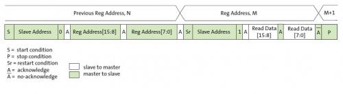
Figure 1: Single READ from Random Location
单次当前位置读取
Figure 2 shows the single READ cycle without writing the address. The internal address will use the previous address value written to the register.

Figure 2: Single Read from Current Location
从任意位置开始连接读取
This sequence (Figure 3) starts in the same way as the single READ from random location . Instead of generating a no-acknowledge bit after the first byte of data has been transferred, the master generates an acknowledge bit and continues to perform byte READs until "L" bytes have been read.

Figure 3: Sequential READ, Start from Random Location
从当前位置开始连接读取
This sequence (Figure 4) starts in the same way as the single READ from current location (Figure 2). Instead of generating a no-acknowledge bit after the first byte of data has been transferred, the master generates an acknowledge bit and continues to perform byte reads until "L" bytes have been read.
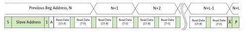
Figure 4: Sequential READ, Start from Current Location
对任意位置写入
Figure 5 shows the typical WRITE cycle from the host to the AP0100CS.The first 2 bytes indicate a 16-bit address of the internal registers with most-significant byte first. The following 2 bytes indicate the 16-bit data.
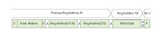
Figure 5: Single WRITE to Random Location
从任意位置开始连续写入
This sequence (Figure 6) starts in the same way as
- AP0100CS图像信号处理器概述(07-27)
- AP0100CS图像信号处理器之功能详解(独家整理)(07-27)
- AP0100CS图像信号处理器全面解读(独家)(08-12)
- Aptina与索尼达成专利交叉许可协议(02-04)
- Aptina从美光科技收购CFA加工和探针成像资产(05-06)
- Aptina完成对美光科技CFA加工和成像传感器资产的收购(07-07)