MAX1470电路调整以及与天线的匹配
时间:04-19
来源:互联网
点击:
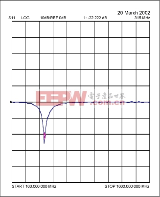
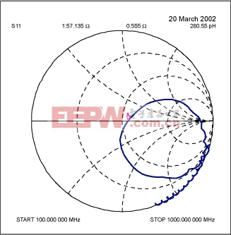
Figure 3. S11 plot of RFIN tuned to 315MHz.

Crystal Pulling
Since the MAX1470 uses a 10.7MHz IF with low-side injection, the crystal frequency is given by (all units in MHz):
For 315MHz applications, the crystal frequency is therefore, 4.7547MHz, while for 433.92MHz a 6.6128MHz crystal is needed.
If the load capacitance that the board presents to the crystal is different than what the crystal was designed for, the crystal is pulled away from its stated operating frequency, introducing an error in the reference frequency. Therefore, to pull the crystal back to its desired operating frequency, external capacitors are added to modify the load capacitance.
Series pulling capacitors , will "speed up" the crystal, while a parallel capacitor will "slow" it down. In the evkit, which presents a 5pF equivalent capacitance, a 3pF load capacitance crystal is used necessitating 2x15pF capacitors in series to speed it up. If these capacitors were not used, the 4.7547MHz crystal will actually oscillate at 4.7544MHz, causing the receiver to be tuned to 314.98MHz instead of 315.0MHz, an error of about 20KHz, or 60ppm. Therefore, on a custom PCB, where the equivalent capacitance is not known, monitor the IF on a spectrum analyzer (make sure to use a DC blocking capacitor before inserting the signal into the spectrum analyzer), and then use series and parallel capacitors to "tune" the IF back to 10.7MHz. Refer to the App note "How to Choose a Crystal for the MAX1470" for more details.
The above modifications should improve the RF performance of the MAX1470 based circuit. For any additional information contact Maxim Integrated Products at 408-737-7600.
模拟电路 模拟芯片 德州仪器 放大器 ADI 模拟电子 相关文章:
- 12位串行A/D转换器MAX187的应用(10-06)
- AGC中频放大器设计(下)(10-07)
- 低功耗、3V工作电压、精度0.05% 的A/D变换器(10-09)
- PIC16C5X单片机睡眠状态的键唤醒方法(11-16)
- 用简化方法对高可用性系统中的电源进行数字化管理(10-02)
- 利用GM6801实现智能快速充电器设计(11-20)
