常用词汇的高速数据转换器条款-Glossary of Fre
时间:05-26
来源:互联网
点击:
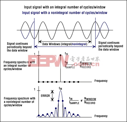
- Synchronous sampling with respect to the input tone (see also Coherent Sampling)
- The capture of a transient signal that fits entirely into the time record
Spurious-Free Dynamic Range (SFDR)
SFDR is the ratio expressed (in dB or dBc) of the rms amplitude of the fundamental (maximum signal component) to the rms value of the next-largest spurious component, excluding DC offset.SSBW
See Small-Signal Input Bandwidth (SSBW).THD
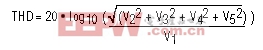
See Total Harmonic Distortion (THD).Total Harmonic Distortion (THD)
THD is typically the ratio (in dB or dBc) of the rms sum of the first four harmonics of the input signal to the fundamental itself. This is expressed as:where V1 is the fundamental amplitude, and V2 through V5 are the amplitudes of the 2nd- through 5th-order harmonics.
TTIMD
See Two-Tone Intermodulation Distortion (TTIMD).Two-Tone Intermodulation Distortion (TTIMD)
Two-tone IMD is the ratio (in dB) of either input tone to the worst 3rd-order (or higher) intermodulation products. Common input-tone amplitudes for the individual input frequencies are at -6.5dB FS or -7dB FS, and their envelope is usually -0.5dB FS.The IMD amplitudes for a two-tone input signal are found at the specified sum and difference frequencies:
fIMF_SUM = |m × fIN1 + n × fIN2|where m and n are positive integers. The condition that m and n are greater than zero creates the 2nd-order (fIN1+fIN2 and fIN1-fIN2) and 3rd-order (2fIN1+fIN2, 2fIN1-fIN2, fIN1+2fIN2 and fIN1-2fIN2, 3fIN1 and 3fIN2) intermodulation products.
fIMF_DIFF = |m × fIN1 - n × fIN2|
Undersampling
Undersampling occurs when the sampling rate of an ADC is much lower (fSAMPLE2 × fIN) than the applied input frequency, usually resulting in a loss of signal information, thereby causing aliasing (see also Aliasing/Anti-Aliasing). With proper filtering and an adequate input tone and clock frequency selection, the aliased components that contain the signal information can be shifted from a higher-frequency band to a lower-frequency band and converted.VCM
See Common-Mode Input Voltage (VCM).VDIFF
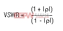
See Differential Input Signal (VDIFF).Voltage Standing-Wave Ratio (VSWR)
VSWR is the ratio of mismatch between the actual impedance and the desired or expected impedance. VSWR is related directly to the reflection coefficient ρ of a simple terminating impedance ZT.ZT depicts the ADC input termination impedance, and ZO represents the transmission-line impedance (nominally 50Ω).
ρ = (ZT - ZO)/(ZT + ZO)
VSWR
See Voltage Standing-Wave Ratio (VSWR).模拟电源 电源管理 模拟器件 模拟电子 模拟 模拟电路 模拟芯片 德州仪器 放大器 ADI 相关文章:
- 采用数字电源还是模拟电源?(01-17)
- 模拟电源管理与数字电源管理(02-05)
- 数字电源正在超越模拟电源(03-19)
- 数字电源PK模拟电源(04-03)
- TI工程师现身说法:采用数字电源还是模拟电源?(10-10)
- 开关电源与模拟电源的分别(05-08)